Safe Operation Practices • Set-Up • Operation • Maintenance • Service • Troubleshooting • Warranty Operator’s Manual Two Stage Snow Thrower — Model 945 SWE WARNING READ AND FOLLOW ALL SAFETY RULES AND INSTRUCTIONS IN THIS MANUAL BEFORE ATTEMPTING TO OPERATE THIS MACHINE. FAILURE TO COMPLY WITH THESE INSTRUCTIONS MAY RESULT IN PERSONAL INJURY. CUB CADET LLC, P.O. BOX 361131 CLEVELAND, OHIO 44136-0019 Printed In USA FORM NO.
1 To The Owner Thank You Thank you for purchasing a Snow Thrower manufactured by Cub Cadet LLC. It was carefully engineered to provide excellent performance when properly operated and maintained. If applicable, the power testing information used to establish the power rating of the engine equipped on this machine can be found at www.opei.org or the engine manufacturer’s web site. Please read this entire manual prior to operating the equipment.
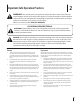
Important Safe Operation Practices 2 WARNING! This symbol points out important safety instructions which, if not followed, could endanger the personal safety and/or property of yourself and others. Read and follow all instructions in this manual before attempting to operate this machine. Failure to comply with these instructions may result in personal injury. When you see this symbol.
Safe Handling of Gasoline 5. To avoid personal injury or property damage use extreme care in handling gasoline. Gasoline is extremely flammable and the vapors are explosive. Serious personal injury can occur when gasoline is spilled on yourself or your clothes which can ignite. Wash your skin and change clothes immediately. Never run an engine indoors or in a poorly ventilated area. Engine exhaust contains carbon monoxide, an odorless and deadly gas. 6.
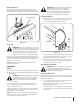
Clearing a Clogged Discharge Chute Hand contact with the rotating impeller inside the discharge chute is the most common cause of injury associated with snow throwers. Never use your hand to clean out the discharge chute. To clear the chute: 1. SHUT THE ENGINE OFF! 2. Wait 10 seconds to be sure the impeller blades have stopped rotating. 3. Always use a clean-out tool, not your hands. Maintenance & Storage 1. Never tamper with safety devices. Check their proper operation regularly.
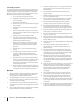
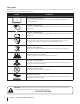
Safety Symbols This page depicts and describes safety symbols that may appear on this product. Read, understand, and follow all instructions on the machine before attempting to assemble and operate. Symbol Description READ THE OPERATOR’S MANUAL(S) Read, understand, and follow all instructions in the manual(s) before attempting to assemble and operate WARNING— ROTATING BLADES Keep hands out of inlet and discharge openings while machine is running.
3 Assembly & Set-Up Contents of Carton • One Snow Thrower • One Engine Operator’s Manual • One Chute Assembly • One Snow Thrower Operator’s Manual • Two Replacement Auger Shear Pins • One Product Registration Card Assembly IMPORTANT: Two replacement auger shear pins are included with this manual (or stowed in the plastic handle panel). Refer to the Maintenance section for more information regarding shear pin replacement.
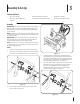
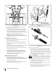
Chute Directional Control 1. Remove the hairpin clip from the spiral control as shown in A of Figure 3-4. 2. Insert the chute directional control rod into the fitting on the spiral control as seen in B of Figure 3-4. 3. Secure with the hairpin clip previously removed. 3. Secure flange keeper removed earlier with lock nuts and screws. Tighten down nuts securing the other two flange keepers. See Figure 3-5. 4.
CAUTION: Operating a snow thrower equipped with steel skid shoes may result in damage to natural stone paver surfaces (e.g. sandstone, bluestone, limestone). Refer to the Replacement Parts or Attachments & Accessories sections for information on available polymer skid shoes. Chute Clean-Out Tool The chute clean-out tool is fastened to the top of the auger housing with a mounting clip and a cable tie at the factory. Cut the cable tie before operating the snow thrower. See Figure 3-8.
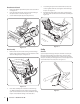
Shift Lever Chute Tilt Control Auger Control Drive Control Auger Control Cable Drive Control Cable Rearward most hole of the actuator brackets Figure 3-10 4. With the auger control in the disengaged “up” position, walk to the front of the machine. 5. Confirm that the auger has completely stopped rotating and shows NO signs of motion. If the auger shows ANY signs of rotating, immediately return to the operator’s position and shut off the engine.
4 Controls and Features Drive Control Speed Selector Shift Lever Two-way Chute Control™ Auger Control Heated Hand Grip Headlight Chute Assembly Wheel Steering Control Chute Directional Control Clean-out Tool Auger Auger Housing Skid Shoe NOTE: For detailed information on all engine controls, refer to the separate Engine Operator’s Manual supplied with this unit.
Auger Control Two-Way Chute Control™ The auger control is located on the left handle. Squeeze the control grip against the handle to engage the augers and start snow throwing action. Release to stop. The two-way chute control is located on the left side of the dash panel and is used to control the distance of snow discharge from the chute. • To change the upper chute angle to control the distance that snow is thrown, pivot the lever forward or backward.
Chute Directional Control The chute directional control is located on the left side of the snow thrower. • To change the direction in which snow is thrown, crank clockwise to discharge to the left and counterclockwise to discharge to the right. Wheel Steering Controls The left and right wheel steering controls are located on the underside of the handles. Squeeze the right control to turn right; squeeze the left control to turn left.
5 Operation Starting and Stopping the Engine Replacing Shear Pins Refer to the Engine Operator’s Manual packed with your snow thrower for instructions on starting and stopping the engine. Each of the auger spiral assemblies are secured to the spiral shaft with a shear pin and bow-tie cotter pin. If the auger should strike a foreign object or ice jam, the snow thrower is designed so that the pins may shear. If the augers will not turn, check to see if the pins have sheared. See Figure 5-1.
6 Maintenance & Adjustments WARNING! Before performing any type of maintenance/service, disengage all controls and stop the engine. Wait until all moving parts have come to a complete stop. Remove the key to prevent unintended starting. Always wear safety glasses during operation or while performing any adjustments or repairs. Engine Refer to the Engine Operators Manual Maintenance section included with the snow thrower.
Shave Plate and Skid Shoes The shave plate and skid shoes on the bottom of the snow thrower are subject to wear. They should be checked periodically and replaced when necessary. 3. 4. Pivot the bracket downward to take up slack in the cable. Retighten the hex nut. Skid Shoes NOTE: The skid shoes on this machine have two wear edges. When one side wears out, they can be rotated 180° to use the other edge. Refer to the Assembly section for instructions on adjusting the skid shoes. 1.
Wheel drive control 4. Refer to the Adjustment section of the Assembly & Set-Up section earlier in this manual for instructions on how to adjust the wheel drive control. To further check the adjustment, proceed as follows: If there is no friction wheel clearance, or the friction wheel does not solidly contact the drive plate, re-adjust the lock nut on the lower end of the drive cable following the instructions in the Assembly section. 5. Reassemble the frame cover. 1.
7 Service Belt Replacement 4. Belt Removal Preparation 1. Disconnect the chute crank assembly at the discharge chute end by removing the hairpin clip and the flat washer. Refer to Figure 7-1. Loosen the bolt shown in Figure 7-3 securing the belt keeper bracket and remove the other bolt. Push the belt keeper bracket up off the engine pulley. Refer to Figure 7-3. Remove Loosen Figure 7-3 Auger Belt Replacement Figure 7-1 2. 3.
2. Slip the auger control belt (the front belt) off the engine pulley. 3. Pull the brake bracket assembly towards the cable guide roller and unhook the auger cable “Z” fitting. Refer to Figure 7-5. 6. Block the impeller with a piece of wood the prevent from spinning and use a 1/2” wrench to remove the hex screw and flat washer from the center of the auger input shaft and auger pulley adapter. Refer to Figure 7-7. B Adapter Post C A Pulley Slot Belt Keeper Figure 7-7 Figure 7-5 4. 5.
11. If also replacing the drive belt, proceed to the “Drive Belt” instruction. If not, reposition the transmission frame back onto the auger housing. Install the drive belt on the engine pulley, re-connect the auger cable “Z” fitting and auger idler rod ferrule to the brake bracket. Reposition and secure the engine pulley belt guard, and re-install the belt cover. NOTE: Make sure to remove the piece of wood blocking the impeller. Check the auger drive belt adjustment.
5. 6. 7. Holding the friction wheel assembly, slide the hex shaft out of the right side of the frame. The spacer on the left side of the hex shaft will fall and the sprocket should remain hanging lose in the chain. Lift the friction wheel assembly out between the axle shaft and the drive shaft assemblies. Remove four screws securing the friction wheel to the hub assembly (refer to Figure 7-11). Discard old friction wheel. 9. Reposition the friction wheel assembly in the snow thrower frame.
8 Troubleshooting Problem Remedy Excessive vibration 1. Loose parts or damaged auger. 1. Stop engine immediately and disconnect spark plug wire. Tighten all bolts and nuts. If vibration continues, have unit serviced by an authorized Service Center. Loss of power 1. Spark plug wire loose. 1. Connect and tighten spark plug wire. 2. Gas cap vent hole plugged. 2. Remove ice and snow from gas cap. Be certain vent hole is clear. 1. Drive control cable in need of adjustment. 1.
9 Replacement Parts Component Part Number and Description 929-0071A Extension Cord, 110V 954-04194A 954-04202 Auger Drive Belt Wheel Drive Belt 918-04178 718-04034 Friction Wheel Assembly Friction Wheel w/Bonded Rubber 725-05326 Lamp 738-04155 714-04040 Shear Pin Bow-tie Cotter Pin 731-07032 Slide Shoe, Deluxe 931-2643 Chute Clean-out Tool 790-00280 Shave Plate, Stainless Steel 731-05632 Key 951-10292 Spark Plug Phone (800) 965-4CUB (4282) to order replacement parts or a complete Parts
10 Attachments & Accessories The following attachments and accessories are available for your Cub Cadet 945 series snow thrower. See your Cub Cadet dealer or the retailer from which you purchased your snow thrower for information regarding price and availability.
Notes 25
MTD CONSUMER GROUP INC (MTD), the California Air Resources Board (CARB) and the United States Environment Protection Agency (U. S. EPA) Emission Control System Warranty Statement (Owner’s Defect Warranty Rights and Obligations) EMISSION CONTROL SYSTEM COVERAGE IS APPLICABLE TO CERTIFIED ENGINES PURCHASED IN CALIFORNIA IN 2005 AND THEREAFTER, WHICH ARE USED IN CALIFORNIA, AND TO CERTIFIED MODEL YEAR 2005 AND LATER ENGINES WHICH ARE PURCHASED AND USED ELSEWHERE IN THE UNITED STATES.
(6) The owner must not be charged for diagnostic labor that leads to the determination that a warranted part is in fact defective, provided that such diagnostic work is performed at a warranty station. (7) The engine manufacturer is liable for damages to other engine components proximately caused by a failure under warranty of any warranted part.
CUB CADET LLC MANUFACTURER’S LIMITED WARRANTY FOR SNOW THROWERS The limited warranty set forth below is given by Cub Cadet LLC with respect to new merchandise purchased and used in the United States, its possessions and territories, and by MTD Products Limited with respect to new merchandise purchased and used in Canada and/or its territories and possessions. This warranty is in addition to any applicable emissions warranty provided with your product.