Safe Operation Practices • Set-Up • Operation • Maintenance • Service • Troubleshooting • Warranty Operator’s Manual Z-Force 54-KH WARNING READ AND FOLLOW ALL SAFETY RULES AND INSTRUCTIONS IN THIS MANUAL BEFORE ATTEMPTING TO OPERATE THIS MACHINE. FAILURE TO COMPLY WITH THESE INSTRUCTIONS MAY RESULT IN PERSONAL INJURY. CUB CADET LLC, P.O. BOX 361131 CLEVELAND, OHIO 44136-0019 Printed In USA Form No.
1 To The Owner Thank You Thank you for purchasing a Cub Cadet Commercial Zero-Turn Tractor. It was carefully engineered to provide excellent performance when properly operated and maintained. Please read this entire manual prior to operating the equipment. It instructs you how to safely and easily set up, operate and maintain your machine. Please be sure that you, and any other persons who will operate the machine, carefully follow the recommended safety practices at all times.
Important Safe Operation Practices 2 WARNING! This symbol points out important safety instructions which, if not followed, could endanger the personal safety and/or property of yourself and others. Read and follow all instructions in this manual before attempting to operate this machine. Failure to comply with these instructions may result in personal injury. When you see this symbol.
12. A missing or damaged discharge cover can cause blade contact or thrown object injuries. 13. Stop the blade(s) when crossing gravel drives, walks, or roads and while not cutting grass. 14. Watch for traffic when operating near or crossing roadways. This machine is not intended for use on any public roadway. 15. Do not operate the machine while under the influence of alcohol or drugs. 16. Mow only in daylight or good artificial light. 17. Never carry passengers. 18. Back up slowly.
Children 1. Tragic accidents can occur if the operator is not alert to the presence of children. Children are often attracted to the machine and the mowing activity. They do not understand the dangers. Never assume that children will remain where you last saw them. a. b. c. d. e. Keep children out of the mowing area and in watchful care of a responsible adult other than the operator. Be alert and turn machine off if a child enters the area.
General Service 1. 2. Before cleaning, repairing, or inspecting, make certain the blade(s) and all moving parts have stopped. Disconnect the spark plug wire and ground against the engine to prevent unintended starting. 3. Periodically check to make sure the blades come to complete stop within approximately (5) five seconds after operating the blade disengagement control. If the blades do not stop within the this time frame, your machine should be serviced professionally by an authorized dealer. 4.
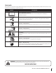
Safety Symbols This page depicts and describes safety symbols that may appear on this product. Read, understand, and follow all instructions on the machine before attempting to assemble and operate. Symbol Description READ THE OPERATOR’S MANUAL(S) Read, understand, and follow all instructions in the manual(s) before attempting to assemble and operate WARNING— ROTATING BLADES Do not put hands or feet near rotating parts or under the cutting deck. Contact with the blade(s) can amputate hands and feet.
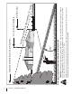
Section 2 — Safe Operation Practices d line (repr esent s a 15 ° slop e) Operate Z-Force zero turn tractors across the face of slopes rather than up and down. Begin with the first pass across the bottom of the slope and turn uphill at the end of each pass whenever possible. WARNING! Do not operate your lawn mower on such slopes. Do not mow on inclines with a slope in excess of 15 degrees (a rise of approximately 2-1/2 feet every 10 feet). A riding mower could overturn and cause serious injury.
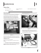
3 Assembly & Set-Up Contents of Crate • One Zero-Turn Tractor • One Engine Operator’s Manual • • One Tractor Operator’s Manual Tractor Preparation 2. Remove the upper crating material from the shipping pallet, and cut any bands or tie straps securing the tractor to the pallet. One Deck Wash Hose Coupler Remove the two shoulder bolts, nuts and spacers securing the seat as shown in Fig. 3-2. Use the lift handle to raise the deck to its highest position.
4. Install lanyard using existing self-tapping screw. See Fig. 3-4. Connecting the Battery Cables California Proposition 65 Warning! Battery posts, terminals, and related accessories contain lead and lead compounds, chemicals known to the State of California to cause cancer and reproductive harm. Wash hands after handling. Existing Selftapping Screw Caution: When attaching battery cables, always connect the POSITIVE (Red) wire to its terminal first, followed by the NEGATIVE (Black) wire.
4 Controls and Features Throttle Control WARNING SLOW Choke Control FAST START CHOKE ON OFF ON NEUTRAL W A R N I N G BRAKE Parking Brake Fuel Shut-Off Valve RH Drive Control Lever Fuel Tank LH Drive Control Lever Deck Lift Pedal PTO Switch STOP RUN START Hour Meter Ignition Switch Deck Height Index Figure 4-1 NOTE: References to LEFT, RIGHT, FRONT, and REAR indicate that Deck Lift Pedal position on the tractor when facing forward while seated in the The deck lift pedal is located on the
Ignition Switch Pull the throttle control handle rearward to decrease the engine speed. The ignition switch is located on the RH console to the right of the operator’s seat. The ignition switch has three positions as follows: Choke Knob The choke knob is located on the left side of the mower next to the operator’s seat. The choke knob controls the position of the engine choke. Pull the knob out to choke the engine; push the knob in to open the choke. OFF — The engine and electrical system is turned off.
Fuel Shut-Off Valve Transmission Bypass Rods (Not Shown) The fuel shut-off valve is located on top of the fuel tank. When turned in a clockwise direction until it stops, it will shut off the flow of fuel to the engine. When turned in a counterclockwise direction it will open and allow fuel to flow to the engine. See Fig. 4-2. The transmission bypass rods (one for each the RH and LH transmission) are located beneath the frame platform, just inside each rear wheel. See Fig. 3-1 on page 9.
5 Operation General Safety • • Before starting the engine or beginning operation, be familiar with the controls. The operator should be in the operator’s seat. The PTO switch must be in the disengaged position, the parking brake engaged, and the RH and LH drive control levers moved to the neutral position. • Keep all shields in place. Keep away from moving parts. • NO RIDERS! Keep all people and pets a safe distance away. Look behind and down to both sides of the tractor before and while backing up.
7. Check if deck is level. When correctly adjusted the mower deck should be level side to side, and the front of the deck should be approximately 1⁄4” lower than the rear of deck. If deck needs to be leveled, refer to the Maintenance & Adjustments section. 5. 6. Push the throttle control to the full forward position. 8. Lubricate all pivot points listed in the Maintenance & Adjustments section. 7. 9.
Move the RH and LH drive control levers to the neutral position. 3. Engage the parking brake. 4. Move the throttle control to midway between the SLOW and FAST positions. 5. Turn the ignition key to the “OFF” position and remove the key from the ignition switch.
1. Driving the Tractor Forward To turn to the left, move the left drive control lever rearward of the right lever. See Fig. 5-3. Warning! Keep all movement of the drive control levers slow and smooth. Abrupt movement of the control levers can affect the stability of the tractor and could cause the tractor to flip over, which may result in serious injury or death to the operator. G ON W A R N I N G START OFF BRAKE FAST Figure 5-3 2.
Driving the Tractor In Reverse Turning While Driving Rearward WARNING! Always look behind and down on both sides of the tractor before backing up. Always look behind while traveling in the reverse direction. To turn the tractor while driving rearward, move the control levers as necessary so that one lever is forward of the other. The tractor will turn in the direction of the forward control lever. 1. 1.
Executing a Zero Turn Executing a “Y” manuever Warning! When executing a zero turn, the tractor MUST BE STOPPED. Executing a zero turn while the tractor is moving can significantly reduce your control of the tractor and will cause severe turf defacement to occur. 1. Stop the forward or reverse motion of the tractor by moving the two drive control levers to neutral. 2. To turn clockwise, move the left control lever forward while simultaneously moving the right control lever rearward. See Fig. 5-8.
Operating The Pto 9. Operate the PTO clutch as follows: 1. Move the throttle control lever to approximately the mid throttle position. 2. Pull the PTO switch upward to the “ENGAGED” position. 3. Advance the throttle lever to the operating speed (full engine speed). 4. The operator must remain in the tractor seat at all times. If the operator should leave the seat without turning off the power take-off switch, the tractor’s engine will shut off. 5.
6 Maintenance & Adjustments Maintenance Schedule Before Each use Check Engine Oil/ Gasoline Level Check Hydraulic Transaxles for leaks Check Tires & Tire Pressure Check Deck, Mower and Hydro Drive Belts Check Blades and Blade Bolt Tightness Check Safety Switches for proper Operation Every 25 Hours Every 50 Hours Every 100 Hours Every 300 Hours After Mowing P P P P P P P P P Check Engine Intake Screen/Cover Clean Mower P Lubricate Wear Points (See Chart) Clean and Re-oil Air Filter’s Foam Precleane
OIL CHART Apply a few drops of SAE engine oil, grease, or use a spray lubricant. Apply the oil to both sides of pivot points. Wipe off any excess. Start engine and operate mower briefly to insure that oil spreads evenly.
Maintenance 8. Warning! Before performing any maintenance or repairs, disengage the PTO, move the drive control levers fully outward in the neutral position, engage the parking brake, stop the engine and remove the key to prevent unintended starting. Refill the engine with new oil. Refer to the Kohler Owner’s Manual for information regarding the volume and weight of engine oil Air Cleaner Service the pre-cleaner and cartridge/air cleaner element as instructed in the Kohler Owner’s Manual.
connected to a water supply. Battery Maintenance • The battery is filled with battery acid and then sealed at the factory. However, if the battery is equipped with fill caps, remove them and check the level of the liquid electrolyte in the battery every 50 operating hours. If the level in any of the six cells has dropped below the bottom of the split ring inside the fill hole, refill the cell with distilled water.
Using the Transmission Bypass Rods Battery Storage If for any reason the tractor will not drive or you wish to move the tractor, the two hydrostatic transmissions are equipped with a bypass rod that will allow you to manually move the tractor short distances. 1. When storing the tractor for extended periods, disconnect the negative battery cable. It is not necessary to remove the battery. 2. All batteries discharge during storage. Keep the exterior of the battery clean, especially the top.
c. Emptying the fuel system: • Prior to putting the tractor in storage, monitor fuel consumption with the goal of running the fuel tank empty. • Close the fuel tank shutoff valve. Disconnect the fuel line from the carburetor and put the end into an approved fuel container. • Open the fuel tank shutoff valve and drain the fuel tank and line into the approved container. Reinstall the fuel line on the carburetor. • Start the engine and allow it to run out of fuel.
Set the seat to the preferred operating position. Leveling the Mower Deck • Adjustment lever is located under the front edge of the seat. • The seat has five inches of front-to-rear adjustment available. When correctly adjusted the mower deck should be level side to side, and the front of the deck should be approximately 1⁄4” lower than the rear of deck. Check factory settings of control levers for the conditions listed above.
8. 9. The final adjustment would be to set the Trailing Link by adjusting the jam nuts on the threaded link. Loosen the jam nuts and tighten the inner nut to achieve the correct length and belt tension. See Fig. 6-6. In many cases it will be necessary to adjust deck height using both eyebolt adjustments and pitch adjustment to achieve the correct blade-to-ground heights. If you remember that the front right blade tip adjustment is fixed and you level to that height, adjusting the decks will be simplified.
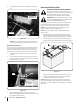
7 Service Battery Removal Jump Starting WARNING!: Failure to use this starting procedure Warning! Battery posts, terminals and related can cause sparking, and the gases in the battery to explode. accessories contain lead and lead compounds. Wash hands after handling. The battery is located on the right/rear of the tractor beneath the seat box frame. To remove the battery: 1. Remove the hold down straps. 2.
Deck Removal 4. Warning! The muffler at the rear of the tractor Remove the four hair pins from the right and left side of the deck lift bracket. See Fig. 7-3. may be extremely hot, and could cause serious burns. Use extreme caution when near the muffler. Allow the muffler to fully cool before removing the belt from the PTO pulley. Deck Lift Bracket Hair Pin Remove the mower deck from the tractor as follows: 1. Apply the parking brake. Remove ignition key and both spark plug caps. 2.
4. Remove the blade drive belt from all the pulleys. 5. Reverse the process to install the belt. See Fig. 7-5 for proper belt routing. Replacing the Blades Warning! Before performing any maintenance, place the PTO switch in the “OFF” position, engage the parking brake lever, turn the ignition key to the “OFF” position and remove the key from the switch. Protect your hands by using heavy gloves when handling the blades.
Sharpening the Blades Changing the Transmission Drive Belt 1. Set the parking brake. 2. Clean any debris from the blades. Keep blades sharp and free of build up at all times. Several components must be removed and special tools used in order to change the tractor’s transmission drive belt. See your Cub Cadet dealer to have the transmission drive belt replaced. 3. Sharpen blades evenly at the original 30° angle to maintain balanced cutting blades. Do not sharpen the underside of the blades.
8 Troubleshooting Problem Engine fails to start Engine runs erratic Cause Remedy 1. PTO/Blade Engage knob engaged. 1. Place knob in disengaged (OFF) position. 2. Parking brake not engaged. 2. Engage parking brake. 3. Drive control levers not fully outward in neutral position. 3. Move drive control levers fully outward in neutral position. 4. Spark plug wire(s) disconnected. 4. Connect wire(s) to spark plug(s). 5. Throttle control lever not in correct starting position. 5.
Problem Engine overheats Remedy 1. Engine oil level low. 1. Fill crankcase with proper amount and weight of oil. 2. Air flow restricted. 2. Clean grass clippings and debris from around the engine’s cooling fins and blower housing. Engine hesitates at high RPM 1. Spark plug(s) gap too close. 1. Remove spark plug(s) and reset the gap. Engine Idles rough 1. Spark plug(s) fouled, faulty or gap too wide. 1. Replace spark plug(s). Set plug gap. 2. Dirty air cleaner. 2.
9 Replacement Parts Component Part Number and Description 759-3336 Spark Plug (Champion RC12YC) KH-24-883-03-S1 Air Filter Element & Pre-Cleaner KH-24-050-13-S Fuel Filter KH-12-050-01-S Oil Filter 02000653 Deck Belt 01005012 PTO Belt 02002648 Drive Belt (Transmissions) 02005018 Blades 918-04426 Deck Spindle Phone (877) 282-8684 to locate your nearest Cub Cadet dealer to order replacement parts or a complete Parts Manual (have your full model number and serial number ready).
Component Part Number and Description 634-3159 Deck Wheel 925-1707D Battery 951-3124E Gas Cap 02000477 02000478 Throttle Control Cable Choke Cable 725-1341B Ignition Key 01006693 Discharge Chute Assembly 02003490 Wheel Assembly 02005000 Caster Wheel Assembly Phone (877) 282-8684 to locate your nearest Cub Cadet dealer to order replacement parts or a complete Parts Manual (have your full model number and serial number ready). Parts Manual downloads are also available free of charge at www.
10 Attachments & Accessories The following attachments and accessories are compatible with your Zero-Turn tractor. See your dealer or the retailer from which you purchased your tractor for information regarding price and availability.
Specifications 11 NOTE: Specifications subject to change without notice.
Notes 12 39
Section 11— Notes
Section 11 — Notes 41
FEDERAL and/or CALIFORNIA EMISSION CONTROL WARRANTY STATEMENT YOUR WARRANTY RIGHTS AND OBLIGATIONS MTD Consumer Group Inc, the United States Environmental Protection Agency (EPA), and, for those products certified for sale in the state of California, the California Air Resources Board (CARB) are pleased to explain the emission (evaporative and/or exhaust) control system (ECS) warranty on your outdoor 2006 and later small off-road spark-ignited engine and equipment (outdoor equipment engine) In California, n
WARRANTED PARTS: The repair or replacement of any warranted part otherwise eligible for warranty coverage may be excluded from such warranty coverage if MTD Consumer Group Inc demonstrates that the outdoor equipment engine has been abused, neglected, or improperly maintained, and that such abuse, neglect, or improper maintenance was the direct cause of the need for repair or replacement of the part.
CUB CADET LLC MANUFACTURER’S LIMITED WARRANTY FOR recon and enforcer ZERO-TURN COMMERCIAL RIDING MOWERs IMPORTANT: To obtain warranty coverage owner must present an original proof of purchase and applicable maintenance records to the servicing dealer. Please see the operator’s manual for information on required maintenance and service intervals.