Safe Operation Practices • Set-Up • Operation • Maintenance • Service • Troubleshooting • Warranty Operator’s Manual Tank S S7232D WARNING READ AND FOLLOW ALL SAFETY RULES AND INSTRUCTIONS IN THIS MANUAL BEFORE ATTEMPTING TO OPERATE THIS MACHINE. FAILURE TO COMPLY WITH THESE INSTRUCTIONS MAY RESULT IN PERSONAL INJURY. CUB CADET LLC, P.O. BOX 361131 CLEVELAND, OHIO 44136-0019 Printed In USA Form No.
1 To The Owner Thank You Thank you for purchasing a Cub Cadet Commercial Zero-Turn tractor. It was carefully engineered to provide excellent performance when properly operated and maintained. Please read this entire manual prior to operating the equipment. It instructs you how to safely and easily set up, operate and maintain your machine. Please be sure that you, and any other persons who will operate the machine, carefully follow the recommended safety practices at all times.
Important Safe Operation Practices 2 WARNING! This symbol points out important safety instructions which, if not followed, could endanger the personal safety and/or property of yourself and others. Read and follow all instructions in this manual before attempting to operate this machine. Failure to comply with these instructions may result in personal injury. When you see this symbol.
15. Mow only in daylight or good artificial light. 16. Never carry passengers. 17. Back up slowly. Always look down and behind before and while backing to avoid a back-over accident. Be aware and pay attention to the safety system function that stops power to the blades when driving in reverse. If not fuctioning properly, contact an authorized dealer for safety system inspection and repair. 18. Slow down before turning. Operate the machine smoothly. Avoid erratic operation and excessive speed. 19.
. Do not mow on wet grass. Reduced traction could cause sliding. 2. Use care when loading or unloading machines onto trailers and trucks. 6. Do not tow heavy pull behind attachments (e.g. loaded dump cart, lawn roller, etc.) on slopes greater than 5 degrees. When going down hill, the extra weight tends to push the tractor and may cause you to loose control (e.g. tractor may speed up, braking and steering ability are reduced, attachment may jack-knife and cause tractor to overturn). 3.
5. 6. 7. Brush Guards and canopies can afford additional protection for the operator. The Brush Guard can deflect tree limbs, clothes lines, and other obstacles that otherwise could come in contact with the ROPS and OPDs. Contact of ROPS and OPDs by items such as tree limbs, clothes lines, guy wires, and buildings, could create hazardous conditions whereby the machine could experience a tipover or roll-over.
4. 5. Regularly check the safety interlock system for proper function, as described later in this manual. If the safety interlock system does not function properly, have your machine serviced. Check the blade(s) and engine mounting bolts at frequent intervals for proper tightness. Also, visually inspect blade(s) for damage (e.g., excessive wear, bent, cracked). Replace the blade(s) with the original equipment manufacturer’s (O.E.M.) blade(s) only, listed in this manual.
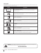
Safety Symbols This page depicts and describes safety symbols that may appear on this product. Read, understand, and follow all instructions on the machine before attempting to assemble and operate. Symbol Description READ THE OPERATOR’S MANUAL(S) Read, understand, and follow all instructions in the manual(s) before attempting to assemble and operate WARNING— ROTATING BLADES Do not put hands or feet near rotating parts or under the cutting deck. Contact with the blade(s) can amputate hands and feet.
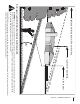
sa 2 0 ˚ slo pe) or a fence post ted l i n e (re p r e s ent dot or a corner of a building... Fo l d a l ong Sight and hold this level with a vertical tree... 20˚ Use this page as a guide to determine slopes where you may not operate safely. WARNING! Do not operate your TANK S Zero-Turn tractor on such slopes. Do not mow on inclines with a slope in excess of 20 degrees (a rise of approximately 3 feet every 10 feet). A riding mower could overturn and cause serious injury.
3 Assembly & Set-Up Contents of Crate • One Zero-Turn Tractor • One Engine Operator’s Manual • One Zero-Turn Tractor Operator’s Manual • One Deck Wash Hose Coupler Tractor Preparation Install Roll Over Protective System (ROPS) Remove the upper crating material from the shipping pallet, and cut any bands or tie straps securing the tractor to the pallet. The Roll Over Protective System (ROPS) has not been installed on your unit for shipping purposes.
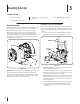
4. Install the upper ROPS section onto the lower ROPS “posts”. Install the (1⁄2-13 x 3.25) HHCS bolts, nuts and washers. See Fig. 3-3. 8. Move the upper ROPS section to the upright position, and insert the locking pins with their retainer hairpin clips. See Fig. 3-5. Hex Bolts Washers Hairpin Clips Locking Pin Nuts Lower ROPS Posts Figure 3-5 Figure 3-3 5. Tighten Upper ROPS section bolts after both RH & LH hardware is installed. 6. Tighten the frame mounting hardware to 80-90 lb.-ft. torque.
Steering Wheel To adjust the distance of the steering wheel column to the operator’s seat: 1. Pull the adjustment lock lever back toward the operator’s position to loosen the column. See Fig. 3-7. Tighten Proper steering column and seat adjustment will result in the following (to adjust the seat see Suspension Seat below): In the neutral position with hands on the steering wheel, • Operator’s upper arms should be relaxed and approximately vertical.
Mechanical Suspension Mechanism 1. To adjust the mechanical suspension mechanism, there is a lever on the front of the seat with an orange colored indicator arrow and guage. 2. Sit down in the operator’s position and look down at the center of the seat, flip the lever out towards the right and pull upward on the fold-out lever and “pump up” to increase seat load capacity and firmness. Push the lever downward to reduce the firmness and load capacity.
4 Controls and Features Roll-Over Protection System Power Implement Lift Cup Holder Fuel Gauge AVOID SERIOUS INJURY OR DEATH IMPLEMENT LIFT BRAKE PUSH TO LOCK, PUSH TO RELEASE PUSH TO STOP • READ THE OPERATOR'S MANUAL, BEFORE USING THE MACHINE. • GO ACROSS, NOT UP AND DOWN SLOPES. • IF MACHINE STOPS GOING UPHILL, STOP BLADES AND BACK DOWN SLOWLY. • AVOID SUDDEN TURNS. • DO NOT MOW WHEN CHILDREN OR OTHERS ARE AROUND. • NEVER CARRY CHILDREN EVEN WITH BLADES OFF.
Speed Control Pedals The speed control pedals are located on the right side of the traction unit. The speed control pedals must be in the neutral position to start the tractor engine. Forward Pedal Reverse Pedal Pushing the forward pedal causes the mower to move forward. Pushing the reverse pedal causes the mower to move backward. Consequently, these pedals control all of the movements of the tractor.
Indicator Lights Indicator lights are provided to notify when conditions of “Low oil pressure”, “High temperature coolant”, “Low alternator output”, and “Glo-plug activation” are present. Glow Plug The glow plug indicator light illuminates when the ignition key is turned to the “RUN” position. The key should not be turned to the “START” position until the light turns off. Oil Pressure The oil pressure indicator light illuminates when the oil pressure is too low. Coolant Temp. The coolant temp.
5 Operation General Safety • RECEIVE INSTRUCTION — Entirely read this operator’s manual. Learn to operate this machine SAFELY. Do not risk INJURY or DEATH. Allow only those who have become competent in its usage to operate this tractor. • Before starting the engine or beginning operation, be familiar with the controls. The operator should be in the operator’s seat. The PTO switch must be in the disengaged position, the parking brake engaged, and the speed control pedals moved to the neutral position.
8. c. Examine the belts for cuts, fraying, and excessive wear. Replace if any of these are detected. 5. Push the throttle control to a position a third of the way between slow and fast. d. Replace the deck cover. 6. Insert the key in the ignition and start switch, turn the switch to “RUN”, and wait for the glo-plug light to go out. 7. Turn the ignition key in a clockwise direction to the “START” position until the engine starts. Check if deck is level.
Stopping the Engine 4. Adjust the operator’s seat to the most comfortable position that allows you to operate the controls. See seat adjustment in the Assembly & Set-Up section. 5. Swing the steering column inward and lock with the adjustable ratchet handle. 1. Place the PTO switch in the “OFF” position. 2. Move the speed control pedals to the neutral position. 3. Engage the parking brake. 4. Move the throttle control to midway between the SLOW and FAST positions. 6.
Turning the Tractor While Driving Forward WARNING! When reversing the direction of travel, we recommend performing gradual ‘U’ turns where possible. Sharper turns increase the possibility of turf defacement, and could affect control of the tractor. ALWAYS slow the tractor before making sharp turns. To turn the tractor while driving forward, use the steering wheel to turn in the direction you wish to travel. 1. To turn to the left, turn the steering wheel counterclockwise (to the operator’s left). 2.
Driving On Slopes 5. Refer to the slope gauge in the Safe Operation Section to help determine slopes where you may not operate safely. NOTE: The speed of the tractor will affect the quality of the mower cut. Mowing at full speed will adversely affect the cut quality. Control the ground speed with the speed control pedals. Warning! Do not operate on inclines with a slope in excess of 20 degrees (a rise of approximately 3 feet every 10 feet). The tractor could overturn and cause serious injury.
Mower Cutting Blades The blades normally “factory installed” on a mower afford the best grass cutting performance on the majority of grasses and mowing conditions; however, there will be occasions whereby the grass type, stage of grass growth, soil conditions, and weather conditions will require different cutting blade types. Since the mower decks are designed so that over-lap of the cutting blades generally exceed 1.5”, there is no need for orientation of one cutting blade to an adjacent blade (I.E.
Reconfigurable Mower Standard set-up Stems (Dandelion, Bahia, Buckhorn, etc.
6 Maintenance & Adjustments Maintenance Schedule Before Each use Check Engine Oil/Gasoline Level Check Hydraulic hoses for leaks Check Tires & Tire Pressure Check Deck, Mower and Hydro Drive Belts Check Blades and Blade Bolt Tightness Check Safety Switches for proper Operation Check Fluid Level in Transaxle Expansion Reservoir Every 25 Hours Every 50 Hours Every 100 Hours Every 500 Hours P P P Clean Mower P Lubricate Wear Points (See Chart) Grease three Spindle Bearings Replace Air Filter Element*
OIL CHART Apply a few drops of SAE engine oil, grease, or use a spray lubricant. Apply the oil to both sides of pivot points. Wipe off any excess. Start engine and operate mower briefly to insure that oil spreads evenly.
LUBRICATION CHART Use a grease-gun filled with NO. 2 Multipurpose Lithium Base Grease Number of Grease Fittings Description EVERY 25 HOURS 3 Blade Spindle Bearings WEEKLY 2 Front Wheels 2 Front Wheel Spindles 2 Mower Deck Ball Wheels Number of Grease Points Description WEEKLY 4 Mowing Deck Pivots 2 Deck Take-Up Idler Pivots 1 Axle Pivot 2 Steering Lever Pivots 1 Hydro Take-up Idler Pivot 1 Park Brake Pivot Spindle Lubricant: Use only Shell Alvania RL 2 grease.
Maintenance Warning! Before performing any maintenance or repairs, disengage the PTO, move the speed control pedals to the neutral position, engage the parking brake, stop the engine and remove the key to prevent unintended starting. Engine Refer to the Yanmar Owner’s Manual for all engine maintenance intervals, procedures, specifications and instructions.
Fuel System Engine Coolant 1. Checking Engine Coolant Level A Fuel Strainer/Water Seperator is provided between the fuel tank and fuel pump. It should be inspected daily and purged of any contaminents. 2. The Fuel Pump provided on the engine is a 12 VDC orbital type. 3. The Main Fuel Filter is a spin-on cartridge. Air Cleaner Service the air cleaner element as instructed in the Yanmar Owner’s Manual. Hydraulic Oil Warning! Never overfill the hydraulic units.
1. Turn the radiator cap counterclockwise to the first stop to release any pressure. 2. Push downward on the cap and turn counter-clockwise until the cap stops then lift cap off. 3. Slowly pour coolant into the filler neck until the level reaches the bottom of the filler neck overflow flange. 1. 4. Wait a few minutes to allow as much air as possible to escape through the filler neck, then reinstall the radiator cap. Place the tractor on a level surface and engage the parking brake. 2.
Contaminants or foreign matter in the oil will also damage the pumps . To prevent this: • Use a filter that captures particles as small as 25 microns or 25 millionths of a meter in diameter. • Be very careful when you remove or repair a component in the hydraulic system. Thoroughly clean off any component before you work on it. • Plug the ends of any hose or line you remove with a rubber or plastic plug. • Use plastic caps to seal off the ends of hydraulic fittings.
The wheel with the leaking tire should be inflated to 20 psi and the wheel placed in a large bucket of water. Carefully inspect the tire, rim and valve for escaping air bubbles which indicate a leak. Mark each leak with a yellow marking crayon and then deflate the tire to 8 psi and repeat the inspection. If the leaks you find are pin hole size to 1⁄16” diameter, the tire can be repaired. If the leaks are larger than 1⁄16” diameter, the tire can be repaired.
Battery Storage Draining The Fuel Filter 1. When storing the tractor for extended periods, disconnect the negative battery cable. It is not necessary to remove the battery. The fuel filter is equipped with a valve to drain condensate (water) that has separated from the diesel fuel and settled at the bottom of the filter. 2. All batteries discharge during storage. Keep the exterior of the battery clean, especially the top. A dirty battery will discharge more rapidly.
7. c. Turn the new filter cartridge approximately 1⁄4-turn clockwise to lock. NOTE: The lock icons on the body and cartridge should be aligned or nearly aligned. 8. Remove the clamp from the fuel line. The filter should begin to fill will diesel fuel. 9. Slowly turn the air bleed knob counterclockwise until fuel begins to seeps out around the bleed knob. Turn the air bleed knob clockwise to close. 10. Remove the catch container and properly dispose of the diesel fuel. 11.
Removing The Tractor From Storage 1. Check the battery. Charge if necessary. 2. Lower tractor off blocks, and inflate the tires to the recommended pressure. 3. Remove the spark plugs and wipe them off. Using the starter, crank the engine to pump the excess oil out of the spark plug holes. Replace the spark plugs and the ignition leads. 4. If drained before storing, fill the fuel tank with clean, fresh gasoline. 5. Check the level of the engine oil in the crankcase and the hydraulic reservoir tank.
2. Loosen the inner jam nuts at the rear left and right of the horizontal threaded rods. See Fig. 6-9. Horizontal Threaded Rod Adjusting the Deck Corner Gauge Wheels Warning! Keep hands and feet away from the discharge opening of the cutting deck. Inner Jam Nut NOTE: The deck gauge wheels are an anti-scalp feature of the deck and are not designed to support the weight of the cutting deck. The mower deck cutting height can be set using the tractor’s power implement lift.
Adjusting the Rear Rollers Removing/Installing the Inner Baffle The rear rollers help prevent the scalping of high spots and uneven terrain across the center section of the deck. The rollers can be adjusted downward or upard 1”. Lowering the roller will increase the striping effect left behind the mower. This positioning of the rear roller will also help to filter the mulched grass clippings into the turf. The inner flow-control baffle can be removed depending on the mowing conditions.
7 Service Battery Removal Jump Starting WARNING! Failure to use this starting procedure can cause sparking, and the gases in the battery to explode. Warning! Battery posts, terminals and related accessories contain lead and lead compounds. Wash hands after handling. The battery is located on the right/rear of the tractor beneath the seat box frame. To remove the battery: 1. Remove the hold down strap. 2.
Seat Switch • • With the speed control pedals in the neutral position, the parking brake engaged and the PTO switch in the “OFF” position, start the engine. Now release the parking brake, hold down on the back of the operator’s seat against spring pressure. Release the operator’s seat and the engine should stop. If the engine does not stop, the seat switch must be replaced. See an authorized service dealer.
Replacing the Blades 4. Warning! Before performing any maintenance, place the PTO switch in the “OFF” position, engage the parking brake lever, turn the ignition key to the “OFF” position and remove the key from the switch. Protect your hands by using heavy gloves when handling the blades. When servicing the mower deck, be careful not to cut yourself on the sharpened blades. 1. Remove the key from the ignition and disconnect the spark plugs. 2.
Changing the Spindle Assembly 1. Jack up the front of the mowing deck about one foot and block it in that position. 2. Make sure the blade clutch is disengaged. 3. Remove the deck cover. 4. Remove the drive belts. (See Replacing the Deck belt.) 5. Remove the blade. (See Replacing the Blades) 6. Using a wrench or socket ratchet remove flange lock nuts, and the four hex flange bolts. Remove the spindle assembly. See Fig. 7-6.
9 Troubleshooting Problem Engine fails to start Engine difficult to start Engine misses under load Engine vapor locks Engine runs unevenly Engine overheats Engine hesitates at high RPM Cause Remedy 1. PTO engaged. 1. Place PTO knob in disengaged (OFF) position. 2. Parking brake not engaged. 2. Engage parking brake. 3. Spark plug wire(s) disconnected. 3. Connect wire(s) to spark plug(s). 4. Throttle control lever not in correct starting position. 4. Place throttle lever in the fast position.
Problem Engine Idles rough Engine fumes are colored (Black) Engine fumes are colored (Blue white) Engine overheats Engine loses power Starter does not work Starter cranks slowly 42 Cause Remedy 1. Spark plug(s) fouled, faulty or gap too wide. 1. Replace spark plug(s). Set plug gap. 2. Dirty air cleaner. 2. Replace air filter. 1. Fuel quality is poor. 1. Replace the poor fuel with the proper fuel. 2. Too much oil. 2. Drain oil until the proper level is reached. 3.
Problem Entire electrical system does not work Dead battery Battery will not take a charge Battery light comes on when the engine is running Indicator lights do not come on when key switch is in START position Excessive vibration Uneven cut Mower will not mulch grass (If Equipped w/Mulching Kit) Cause Remedy 1. Blow fuse. 1. Replace the fuse. 2. Loose or corroded connections. 2. Repair or replace the connections. 3. Sulfated or worn out battery. 3.
10 Replacement Parts Component Part Number and Description YA-119802-55801 Fuel Filter YA-129150-35153 Oil Filter YA-129242-55730 Water Separator Element 01007937 Deck Belt 954-04267 Drive Belt 954-04255 PTO Belt 02000568 Blade, 25.0 02000588 Deck Spindle Phone (800) 800-7310 to order replacement parts or a complete Parts Manual (have your full model number and serial number ready). Parts Manual downloads are also available free of charge at www.mtdproducts.com.
Component Part Number and Description 634-3159 Deck Wheel 925-0453G Battery 02001081 Gas Cap 02001133P Throttle Control 725-1341B Ignition Key 01009705P Discharge Chute Assembly 02002668 Wheel Assembly 02003396 Wheel Assembly Phone (800) 800-7310 to order replacement parts or a complete Parts Manual (have your full model number and serial number ready). Parts Manual downloads are also available free of charge at www.mtdproducts.com.
10 Attachments & Accessories The following attachments and accessories are compatible with your TANK S tractor. See your dealer or the retailer from which you purchased your tractor for information regarding price and availability.
Notes 11 47
Section 11— Notes
Section 11 — Notes 49
FEDERAL and/or CALIFORNIA EMISSION CONTROL WARRANTY STATEMENT YOUR WARRANTY RIGHTS AND OBLIGATIONS MTD Consumer Group Inc, the United States Environmental Protection Agency (EPA), and, for those products certified for sale in the state of California, the California Air Resources Board (CARB) are pleased to explain the emission (evaporative and/or exhaust) control system (ECS) warranty on your outdoor 2006 and later small off-road spark-ignited engine and equipment (outdoor equipment engine) In California, n
WARRANTED PARTS: The repair or replacement of any warranted part otherwise eligible for warranty coverage may be excluded from such warranty coverage if MTD Consumer Group Inc demonstrates that the outdoor equipment engine has been abused, neglected, or improperly maintained, and that such abuse, neglect, or improper maintenance was the direct cause of the need for repair or replacement of the part.
CUB CADET LLC MANUFACTURER’S LIMITED WARRANTY FOR tank ZERO-TURN COMMERCIAL RIDING MOWER IMPORTANT: To obtain warranty coverage owner must present an original proof of purchase and applicable maintenance records to the servicing dealer. Please see the operator’s manual for information on required maintenance and service intervals. In the U.S.A.: Check your Yellow Pages, or contact Cub Cadet LLC at P.O. Box 361131, Cleveland, Ohio 44136-0019, call 1-877-282- 8684 or log on to our website at www.cubcadet.