Safe Operation Practices • Set-Up • Operation • Maintenance • Service • Troubleshooting • Warranty Operator’s Manual Hydrostatic Lawn Tractor — LTX1042KW, LTX1045 & LTX1046M WARNING READ AND FOLLOW ALL SAFETY RULES AND INSTRUCTIONS IN THIS MANUAL BEFORE ATTEMPTING TO OPERATE THIS MACHINE. FAILURE TO COMPLY WITH THESE INSTRUCTIONS MAY RESULT IN PERSONAL INJURY. CUB CADET LLC, P.O. BOX 361131 CLEVELAND, OHIO 44136-0019 Printed In USA Form No.
1 To The Owner Thank You Thank you for purchasing a Cub Cadet Lawn Tractor. It was carefully engineered to provide excellent performance when properly operated and maintained. If applicable, the power testing information used to establish the power rating of the engine equipped on this machine can be found at www.opei.org or the engine manufacturer’s web site. Please read this entire manual prior to operating the equipment.
Important Safe Operation Practices 2 WARNING! This symbol points out important safety instructions which, if not followed, could endanger the personal safety and/or property of yourself and others. Read and follow all instructions in this manual before attempting to operate this machine. Failure to comply with these instructions may result in personal injury. When you see this symbol.
12. A missing or damaged discharge cover can cause blade contact or thrown object injuries. 13. Stop the blade(s) when crossing gravel drives, walks, or roads and while not cutting grass. 14. Watch for traffic when operating near or crossing roadways. This machine is not intended for use on any public roadway. Slopes are a major factor related to loss of control and tip-over accidents which can result in severe injury or death. All slopes require extra caution.
Service Children 1. Tragic accidents can occur if the operator is not alert to the presence of children. Children are often attracted to the machine and the mowing activity. They do not understand the dangers. Never assume that children will remain where you last saw them. a. Keep children out of the mowing area and in watchful care of a responsible adult other than the operator. b. Be alert and turn machine off if a child enters the area. c.
Periodically check to make sure the blades come to complete stop within approximately (5) five seconds after operating the blade disengagement control. If the blades do not stop within the this time frame, your machine should be serviced professionally by an authorized MTD Service Dealer. Do not modify engine 4. Check brake operation frequently as it is subjected to wear during normal operation. Adjust and service as required. Notice Regarding Emissions 5.
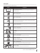
Safety Symbols This page depicts and describes safety symbols that may appear on this product. Read, understand, and follow all instructions on the machine before attempting to assemble and operate. Symbol Description READ THE OPERATOR’S MANUAL(S) Read, understand, and follow all instructions in the manual(s) before attempting to assemble and operate DANGER— ROTATING BLADES Never carry passengers. Never carry children, even with the blades off.
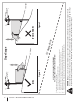
Section 2 — Important Safe Operation Practices Figure 1 line Figure 2 (TOO STEEP) 15° Slope WARNING! Slopes are a major factor related to tip-over and roll-over accidents which can result in severe injury or death. Do not operate machine on slopes in excess of 15 degrees. All slopes require extra caution. If you cannot back up the slope or if you feel uneasy on it, do not mow it. Always mow up and down slopes, never across the face of slopes. To check the slope, proceed as follows: 1.
3 Assembly & Set-Up Contents of Crate • One Lawn Tractor • • One Lawn Tractor Operator’s Manual • One Oil Drain Tube One Deck Wash Hose Coupler One Engine Operator’s Manual Tractor Set-Up CAUTION: Never attempt to move the tractor manually without first opening the hydrostatic relief valve. Doing so will result in serious damage to the tractor’s transmission.
Connecting the Battery Cables Checking Tire Pressure WARNING! Do not overinflate tires. Check sidewall of tires for maximum psi. Equal tire pressure should be maintained at all times. CALIFORNIA PROPOSITION 65 WARNING! Battery posts, terminals, and related accessories contain lead and lead compounds, chemicals known to the State of California to cause cancer and reproductive harm. Wash hands after handling.
Adjusting the Seat Gas and Oil To adjust the position of the seat, pull up and hold the seat adjustment lever. Slide the seat forward or rearward to the desired position; then release the adjustment lever. Make sure seat is locked into position before operating the tractor. See Figure 3-5. The fuel tank is located under the hood. Remove the fuel cap by turning it counterclockwise. Use only clean, fresh (no more than 30 days old), unleaded gasoline. Do not overfill the tank.
4 Controls & Features Systems Indicator Monitor Fuel Tank Cap Ignition Switch Module Choke Control Throttle/Choke Control Fuel Level Indicator Drive Pedal Brake Pedal Cargo Net Parking Brake/ Cruise Control Lever Seat Adjustment Lever Reverse Pedal Deck Lift Lever PTO (Blade Engage) Handle Storage Bin Cup Holder Figure 4-1 The Lawn Tractor controls and features are illustrated in Figure Choke Control 4-1 and described on the following pages.
Deck Lift Lever Systems Indicator Monitor/Hour Meter LCD Found on your tractor’s right fender, the deck lift lever is used to change the height of the cutting deck. To use, move the lever to the left, then place in the notch best suited for your application. Ignition Switch Module WARNING! Never leave a running machine unattended. Always disengage PTO, set parking brake, stop engine and remove key to prevent unintended starting.
Fuel Level Indicator Parking Brake/Cruise Control Lever The Fuel Level Indicator is located on the left side of the tractor’s dash and indicates the amount of fuel in the gas tank. PTO/Blade Engage Handle Activating the PTO engages power to the cutting deck or other (separately available) attachments. Push forward on the PTO/Blade Engage handle to activate it. Pull the PTO/Blade Engage handle back to disengage the power to the cutting deck or other (separately available) attachments.
5 Operation Starting the Engine TO AVOID SERIOUS INJURY OR DEATH • • • • • • • • • GO UP AND DOWN SLOPES, NOT ACROSS. AVOID SUDDEN TURNS. DO NOT OPERATE THE UNIT WHERE IT COULD SLIP OR TIP. IF MACHINE STOPS GOING UPHILL, STOP BLADE(S) AND BACK DOWNHILL SLOWLY. KEEP SAFETY DEVICES (GUARDS, SHIELDS, AND SWITCHES, ETC.) IN PLACE AND WORKING. REMOVE OBJECTS THAT COULD BE THROWN BY THE BLADE(S). KNOW LOCATION AND FUNCTION OF ALL CONTROLS.
Driving The Tractor Reverse Caution Mode WARNING! Avoid sudden starts, excessive speed and sudden stops. The REVERSE CAUTION MODE position of the key switch module allows the tractor to be operated in reverse with the blades (PTO) engaged. NOTE: Mowing in reverse is not recommended. 1. Lightly press the brake pedal to release the parking brake. Move the throttle lever into the FAST (rabbit) position. 2. To travel FORWARD, slowly press the drive pedal forward until the desired speed is achieved.
Driving On Slopes Cruise Control WARNING! Never engage the cruise control lever while traveling in reverse. Refer to the SLOPE GAUGE on page 8 to help determine slopes where you may operate the tractor safely. WARNING! Do not mow on inclines with a slope in excess of 15 degrees (a rise of approximately 2-1⁄2 feet every 10 feet). The tractor could overturn and cause serious injury. To set the cruise control: 1. Slowly press the drive pedal with your right foot until the desired speed is achieved.
Engaging the PTO Engaging the PTO transfers power to the cutting deck or other (separately available) attachments. To engage the PTO: 1. Move the Throttle/Choke control, or Throttle control lever to the FAST (rabbit) position. 2. Push the PTO/Blade Engage lever forward into the engaged (ON) position.
6 Maintenance & Adjustments Maintenance Schedule Before Each use Every 10 Hours Check Air Filter for Dirty, Loose or Damaged Parts Every 50 Hours Every 100 Hours P Clean Hood/Dash Louvers Check Engine Oil Level Every 25 Hours Prior to Storing P P P P Clean and Re-oil Air Filter’s Foam Precleaner P Replace Air Filter Element P Change Engine Oil and Replace Oil Filter Clean Battery Terminals P P P P Lube Front Axles and Rims Clean Engine Cooling Fins Lube Front Deck Wheels Lube Pedal Pivot P
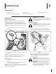
3. Pop open the protective cap on the end of the oil drain valve to expose the drain port. See Figure 6-1 Spark Plug The spark plug should be cleaned and the gap reset once a season. Refer to the Kohler Owner’s Manual for correct plug type and gap specifications. Hydrostatic Transmission The hydrostatic transmission is sealed at the factory and is maintenance-free. The fluid level cannot be checked and the fluid cannot be changed.
3. Attach the hose coupler to the water port on your decks surface. See Figure 6-2. Lubrication WARNING! Before lubricating, repairing, or inspecting, always disengage PTO, set parking brake, stop engine and remove key to prevent unintended starting. Front Wheels Each of the front wheel axles and rims is equipped with a grease fitting. See Figure 6-3. Lubricate with a No. 2 multi-purpose grease applied with a grease gun after every 25 hours of tractor operation. Figure 6-2 4. Turn the water on. 5.
Adjustments WARNING! Shut the engine off, remove the ignition key and engage the parking brake before making adjustments. Protect your hands by using heavy gloves when handling the blades. 2. Measure the distance from the outside of the left blade tip to the ground and the distance from the outside of the right blade tip to the ground. Both measurements taken should be equal. If they’re not, proceed to the next step. 3. Loosen, but do NOT remove, the hex bolt on the left deck hanger bracket.
Steering Adjustment Off-Season Storage If the tractor turns tighter in one direction than the other, or if the ball joints are being replaced due to damage or wear, the steering drag links may need to be adjusted. Before storing the machine for an extended period: Adjust the drag links so that equal lengths of each are threaded into the ball joint on the left side and the ball joint on the right side: 1.
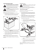
7 Service Cutting Deck Removal 1. Place the PTO/Blade Engage lever in the disengaged (OFF) position and engage the parking brake. 2. Lower the deck by moving the deck lift lever into the bottom notch on the right fender. 3. Locate the engine pulley under the front of your tractor. See Figure 7-1.
6. Pull the deck support pin outward to release the deck from the deck lift arm. See Figure 7-3. Deck Lift Arm Deck Support Pin Figure 7-5 11. Gently slide the cutting deck (from the right side) out from underneath the tractor. Reinstall the belt keeper rod loosened earlier. Figure 7-3 7. Repeat the above steps on the tractor’s right side. 12. 8. Move the deck lift lever into the top notch to raise the deck lift arms up and out of the way. Changing the Deck Belt 9.
3. It may also be necessary to loosen the hex nut on the left idler pulley to get the belt off the pulley and around the belt guard. 4. Carefully remove the deck belt from around the two spindle pulleys and the two deck idler pulleys. See Figure 7-6. 10. Place the belt into the engine pulley. See Figure 7-8. PTO Belt Rotate Pulley Figure 7-8 11. Replace the belt guard. See Figure 7-1.
NOTE: When replacing the blade, be sure to install the blade with the side of the blade marked ‘‘Bottom’’ (or with a part number stamped in it) facing the ground when the mower is in the operating position. CAUTION: Use a torque wrench to tighten the blade spindle hex flange nut to between 70 ft-lbs and 90 ft-lbs.
Tires Charging WARNING! Batteries give off an explosive gas while charging. Charge the battery in a well ventilated area and keep away from an open flame or pilot light as on a water heater, space heater, furnace, clothes dryer or other gas appliances. CAUTION: When charging your tractor’s battery, use only a charger designed for 12V lead-acid batteries. Read your battery charger’s Owner’s Manual prior to charging your tractor’s battery. Always follow its instructions and heed its warnings.
8 Troubleshooting Problem Engine fails to start Cause Remedy 1. PTO/Blade Engage knob engaged. 1. Place knob in disengaged (OFF) position. 2. Parking brake not engaged. 2. Engage parking brake. 3. Spark plug wire(s) disconnected. 3. Connect wire(s) to spark plug(s). 4. Throttle/Choke control or Throttle lever not in the correct starting position. 4. Place the Throttle/Choke control, or Throttle lever in the FAST position. 5. Choke not activated 5.
9 Replacement Parts Component Part Number and Description 759-3336 KM-BPR4ES Spark Plug (Champion RC12YC) (Kohler) Spark Plug (BPR4ES (NGK)) (Kawasaki) KH-20-883-02-S1 Air Cleaner Element with Pre-cleaner (Kohler Single Cylinder) KH-32-883-03-S1 Air Filter Element and Pre-cleaner (Kohler Twin Cylinder) KM-11013-7050 Air Filter Element (Kawasaki Twin Cyl.) KH-12-050-01-S Oil Filter (Kohler Single & Twin Cyl.
Component Part Number and Description 734-04155 Deck Wheel (Front) 734-0973 Deck Wheel (Rear) 925-1707D Battery 951-12179A 751-0603A 951-12426 Fuel Tank Cap (Kaw. & Kohl. Twin Cyl.) Fuel Tank Cap (Kohler Single Cyl.) Fuel Tank Cap (Kohl.
10 Attachments & Accessories The following attachments and accessories are compatible for Cub Cadet LTX1042KW, LTX1045 and LTX1046M. See your Cub Cadet dealer or the retailer from which you purchased your tractor for information regarding price and availability. CAUTION: Cub Cadet Series 1000 lawn tractors are NOT designed for use with any type of ground-engaging attachments (e.g. tiller or moldboard plow). Use of this type of equipment WILL void the tractor’s warranty.
FEDERAL and/or CALIFORNIA EMISSION CONTROL WARRANTY STATEMENT YOUR WARRANTY RIGHTS AND OBLIGATIONS MTD Consumer Group Inc, the United States Environmental Protection Agency (EPA), and, for those products certified for sale in the state of California, the California Air Resources Board (CARB) are pleased to explain the emission (evaporative and/or exhaust) control system (ECS) warranty on your outdoor 2006 and later small off-road spark-ignited engine and equipment (outdoor equipment engine) In California, n
10. Add-on or modified parts that are not exempted by the Air Resources Board may not be used. The use of any non-exempted add-on or modified parts by the ultimate purchaser will be grounds for disallowing a warranty claims. MTD Consumer Group Inc will not be liable to warrant failures of warranted parts caused by the use of a non-exempted add-on or modified part.
CUB CADET LLC MANUFACTURER’S LIMITED WARRANTY FOR SERIES 1000 & SERIES 1500 TRACTORS IMPORTANT: To obtain warranty coverage owner must present an original proof of purchase and applicable maintenance records to the servicing dealer. Please see the operator’s manual for information on required maintenance and service intervals.
Medidas importantes de seguridad • Configuración • Funcionamiento • Mantenimiento • Servicio • Solución de problemas • Garantía Manual del Operador Tractor Corta Césped Hidrostático LTX1042KW, LTX1045 & LTX1046M ADVERTENCIA LEA Y SIGA TODAS LAS INSTRUCCIONES DE ESTE MANUAL ANTES DE PONER EN FUNCIONAMIENTO ESTA MÁQUINA. SI NO RESPETA ESTAS INSTRUCCIONES PUEDE PROVOCAR LESIONES PERSONALES. CUB CADET LLC, P.O.
1 Al propietario Gracias Gracias por comprar una Cub Cadet tractor corta césped. El mismo ha sido diseñado cuidadosamente para brindar excelente rendimiento si se lo opera y mantiene correctamente. Por favor lea todo este manual antes de operar el equipo. Le indica cómo configurar, operar y mantener la máquina con seguridad y fácilmente.
2 Medidas importantes de seguridad ADVERTENCIA: La presencia de este símbolo indica que se trata de instrucciones importantes de seguridad que se deben respetar para evitar poner en peligro su seguridad personal y/o material y la de otras personas. Lea y siga todas las instrucciones de este manual antes de poner en funcionamiento esta máquina. Si no respeta estas instrucciones puede provocar lesiones personales. Cuando vea este símbolo.
10. Esté atento a la cortadora y a la dirección de la descarga de los aditamentos y no apunte a nadie. Nunca opere la cortadora de césped sin que estén en su lugar apropiado la cubierta de descarga o el colector de recortes de césped. 11. No ponga las manos o los pies cerca de las piezas rotatorias o debajo de la plataforma de corte. El contacto con las cuchillas puede producir la amputación de manos y pies. 12.
6. 7. No cambie a transmisión neutral para descender. El exceso de velocidad puede hacer que el operador pierda el control de la máquina, ocasionando lesiones graves e incluso la muerte. No remolque cargas pesadas detrás de los aditamentos (carrito de basura cargado, podadora de rodillos, etc) en pendientes mayores de 5 grados.
2. 3. 4. 5. 6. 7. 8. 9. 10. 11. 12. 13. 14. Antes de limpiar, reparar o inspeccionar la máquina, compruebe que la(s) cuchilla(s) y todas las partes en movimiento se hayan detenido. Desconecte el cable de la bujía y póngalo haciendo masa contra el motor para evitar que se encienda accidentalmente. Revise periódicamente para asegurarse que las cuchillas se detengan por completo en aproximadamente cinco (5) segundos después de accionar el control de desenganche de la(s) cuchilla(s).
Símbolos De Seguridad Esta página representa y describe la seguridad los símbolos que pueden parecer en este producto. Lea, comprenda, y siga todas instrucciones de la máquina antes de intentar ensamblar y operar. Symbol Description LEA EL MANUAL(S) DEL OPERADOR leído, entienda, y siga todas las instrucciones en el manual(s) antes de procurar montar y funcionar PELIGRO— DÉ EL CORTE DE PIE Nunca transporte pasajeros. Nunca transporte niños, aún con la cuchilla apagada.
(ACEPTAR) Figura 1 Figura 2 (DEMASIADO ESCARPADO) Pendiente de Calibre 15° Pendiente ea 15° lí n ua di s c o n tin USO DE ESTE PENDIENTE DE CALIBRE PARA DETERMINAR SI UNA PENDIENTE ES DEMASIADO ESCARPADO PARA UNA OPERACIÓN SEGURA! Para comprobar la pendiente, haga lo siguiente: 1. Borrar esta página y doble a lo largo de la línea discontinua. 2. Localizar un objeto vertical sobre o detrás de la pendiente (un poste, un edificio, una valla, un árbol, etc.) 3.
3 Montaje y Configuración Contenido del cajón • Un tractor corta césped • Un tubo de drenaje de aceite • Un Manual del operador del tractor corta césped • Un Manual del operador del motor Configuración del tractor 1.
Instalación del cable de la baterías Control de la presión de los neumáticos PROPUESTA 65 DE CALIFORNIA ADVERTENCIA! Los postes de la batería, terminales y accesorios relacionados contienen plomo y compuestos químicos, conocidos por el Estado de California que causan cáncer y daños en la reproducción. Lávese las manos después de la manipulación.
c. Coloque la palanca de elevación de la plataforma en el ajuste de altura de corte deseado. d. Vuelva a insertar el tornillo con reborde (con cada rueda de calibración) dentro del orificio de posicionamiento que deja aproximadamente ½ pulgada entre la parte inferior de la rueda y el pavimento. Consulte la sección Nivelación de la plataforma en la sección Mantenimiento de este manual para obtener instrucciones detalladas sobre diferentes ajustes de la plataforma.
4 Controles y Características Monitor del indicador de sistemas Tapón del tanque de combustible Módulo del interruptor de encendido Control del cebado r Control del regulado r/cebador Pedal de la transmisión Indicador de nivel de combustible Pedal de la marcha atrás Pedal de freno Cargo Neto Palanca de ajuste del asiento Freno de mano / palanca de control de crucero Bin almacenamiento Palanca de elevación de la plataforma Manija de potencia de arranque (PTO)/ enganche de cuchilla Ahueque a Poseed
Palanca de elevación de la plataforma Pedal de la marcha atrás Ubicada en el guardabarros derecho del tractor, la palanca de elevación de la plataforma se utiliza para cambiar la altura de la plataforma de corte. Para utilizarla, mueva la palanca hacia la izquierda, luego colóquela en la muesca que mejor se adapte a la aplicación deseada. El pedal la marcha atrás reverso está situado en el derecho del tractor a lo largo del tablero corriente.
Aceite Freno de mano/palanca de control de crucero Es normal que la luz de aceite se ilumine cuando el motor está girando durante el arranque, pero si se ilumina durante la operación, cuando el motor está funcionando, detenga el tractor de inmediato y controle el nivel de aceite del motor según las instrucciones de este Manual del Propietario.
5 Funcionamiento ADVERTENCIA PARA EVITAR LESIONES PERSONALES GRAVES O LA MUERTE • EN LAS PENDIENTES PODE HACIA ARRIBA Y HACIA ABAJO, NO DE FORMA TRANSVERSAL. • EVITE MANIOBRAS DE GIRO BRUSCAS. • NO OPERE LA UNIDAD EN ÁREAS DONDE PUEDE DERRAPAR O TROPEZAR • SI LA MÁQUINA DEJA DE SUBIR LA PENDIENTE, DETENGA LA(S) CUCHILLA(S) Y RETROCEDA LENTAMENTE CUESTA ABAJO • MANTENGA TODOS LOS DISPOSITIVOS DE SEGURIDAD (PROTECCIONES, ESCUDOS, INTERRUPTORES, ETC.) EN SU LUGAR Y EN CORRECTO FUNCIONAMIENTO.
Conducción del tractor Modo de precaución en marcha atrás ¡ADVERTENCIA! Evite arrancar súbitamente, desarrollar excesiva velocidad y detenerse de repente. 1. 2. Presione levemente el pedal del freno para liberar el freno de mano. Mueva la palanca del regulador a la posición FAST (VELOCIDAD RÁPIDA, representada por una liebre). La posición MODO DE PRECAUCIÓN EN MARCHA ATRÁS del módulo del interruptor de llave permite operar el tractor en marcha atrás con las cuchillas (toma de fuerza - PTO) enganchadas.
El MODO DE PRECAUCIÓN EN MARCHA ATRÁS permanece activado hasta que: a. Se coloque la llave en la posición CORTE NORMAL o en la posición STOP (detención) o b. El operador abandona el asiento. Operación en pendientes Después de completar el paso 3, el pedal de freno debe permanecer en posición abajo. Si no lo hace, el freno de mano no estáenganchado. Repita los pasos 1-4 para enganchar el freno de mano. Para desenganchar el freno de mano, presione levemente el pedal de freno.
Utilización de la palanca de elevación de la plataforma Corte de césped ¡ADVERTENCIA! Para tratar de evitar el contacto con las cuchillas o una lesión por algún objeto que sea arrojado, mantenga a los observadores, a los ayudantes, niños y mascotas alejados al menos 25 metros de la máquina mientras está en funcionamiento. Detenga la máquina si alguien se acerca.
6 Mantenimiento y Ajustes Calendario de mantenimiento Antes de cada uso Controle el filtro de aire para ver si hay piezas sucias, sueltas o dañadas Cada 25 horas Cada 50 horas Antes de almacenar P P P Limpie y vuelva a lubricar el depurador de espuma del filtro de aire P P Reemplace el elemento del filtro de aire Cambie el aceite del motor y reemplace el filtro de aceite Limpie los bornes de la batería P P P P P Lubrique los ejes frontales y las llantas Limpie las aletas de refrigeración del mot
2. Abra el capó del tractor y ubique el puerto de drenaje de aceite del lado izquierdo del motor. 3. Abra el tapón protector en el extremo de la válvula de drenaje de aceite para dejar expuesto el orificio de drenaje. Vea la Figura 6-1. Depurador de aire Realice el servicio de mantenimiento del prefiltro y del elemento del depurador de aire/ cartucho según las instrucciones del Manual del Propietario Kohler. Bujía de encendido Se debe limpiar la bujía y reajustar la separación una vez por temporada.
Smart Jet 10. La plataforma de su tractor está equipada con un puerto de agua sobre su superficie como parte del sistema de lavado de la plataforma. Gire la llave de encendido a la posición STOP (detención) para apagar el motor del tractor. 11. Desconecte el agua y retire el acoplador de la manguera desde el puerto de agua que se encuentra en la superficie de la plataforma. 12. Repita los pasos 4-11 en el otro lado de la cubierta.
Ajustes 4. ¡ADVERTENCIA! Apague el motor, retire la llave de encendido y coloque el freno de mano antes de realizar ajustes. Proteja sus manos utilizando guantes pesados cuando maneje las cuchillas. NOTA: Controle la presión de neumáticos del tractor antes de realizar cualquier nivelación de la plataforma. Consulte la sección Neumáticos en la Servicio Seccion para obtener información sobre la presión de los neumáticos.
4. Ajuste del freno de mano Si el tractor no se detiene por completo cuando se presiona totalmente el pedal de freno, o si las ruedas traseras del tractor siguen rodando con el freno de mano colocado (y la válvula de descarga hidrostática abierta) el freno necesita ajustes. Consulte con su distribuidor Cub Cadet para realizar un ajuste correcto del freno. Ajuste del asiento Consulte la sección Configuración y Montaje de este manual para ver instrucciones para el ajuste del asiento.
7 Servicio Extracción de la plataforma de corte NOTA: Si hay demasiada tensión en la correa para que sea quitada fácilmente de la polea del motor, inserte cuidadosamente” llave de trinquete de impulsión un 3⁄8 (fije para apretar) en la perforación rectangular encontrada en el soporte más ocioso de la cubierta izquierda y gírelo hacia el derecho del tractor para relevar la tensión en la correa. Vea Figura 7-2. Para extraer la plataforma de corte, proceda de la siguiente manera: 1.
6. Tire hacia afuera el pasador de soporte de la plataforma para separar la misma del brazo de elevación de la plataforma. Vea la Figura 7-3. Brazo de elevación de la plataforma Pasador de soporte de la plataforma Figura 7-5 11. Figura 7-3 7. Repita los pasos anteriores del lado derecho del tractor. 8. Mueva la palanca de elevación de la plataforma dentro de la muesca superior para levantar los brazos de elevación de la plataforma y retirarlos del paso. 9.
5. Pruebe el equilibrio de la cuchilla usando un compensador de cuchillas. Afile el metal del lado pesado hasta que quede bien equilibrada. NOTA: Cuando reemplace la cuchilla, asegúrese de instalarla con el lado marcado “Bottom” (inferior) (o con el lado que posee un número de pieza estampado) mirando al piso cuando la cortadora de césped está en posición de operación.
Batería Carga de la batería ¡ADVERTENCIA! Al cargarse, las baterías emiten un gas que puede causar explosiones. Cargue la batería en un área bien ventilada y aléjela de una llama abierta o luz piloto, como por ejemplo calentadores de agua, calefactores de ambiente, hornos, secadores de ropa u otros aparatos a gas.
Neumáticos ¡ADVERTENCIA! No sobrepasar nunca la presión máxima de inflado figuran en el flanco del neumático. Hexagonal Tornillos Refiérase a la pared del neumático para la ISP recomendados o máximos fabricante de neumáticos es exacto. No inflar demasiado. Cinturón de la Guardia La presión del neumático desigual podría causar que la plataforma de corte para cortar de manera desigual.
5. 6. Para colocar la nueva correa comience encaminando la correa alrededor de las dos poleas de huso externas, entonces alrededor de la polea de huso delantera según las indicaciones de Figura 7-9. 10. Entonces encamine la correa alrededor de las dos poleas más ociosas de la cubierta como demostración en Figura 7-9. Vuelva una instalar la cubierta de la siguiente Manera: a. La Cubierta bajo Con el chasis del Cortacésped, Adjunte la barra estabilizadora. Véase la Figura 7-5. b.
8 Solución de Problemas Problem Cause Remedy 1. Palanca de potencia de arranque (PTO) / enganche de cuchilla conectada. 1. Coloque la palanca en la posición de desconexión (OFF). 2. No está colocado el freno de mano. 2. Coloque el freno de mano. 3. Se ha desconectado el cable de la bujía. 3. Conecte el cable a la bujía. 4. Acelerador / cebador no la palanca de control o del acelerador en la posición inicial correcta. 4.
Problem Vibración excesiva La cortadora de césped no procesa los recortes como abono Corte desigual Cause 1. Cuchilla de corte floja o descentrada. 1. Apriete la cuchilla y el husillo. 2. Cuchilla dañada o curvada. 2. Reemplace la cuchilla. 1. La velocidad del motor es demasiado lenta. 1. Throttle lugar / Control del estrangulador, o el control del acelerador, en el FAST (liebre). 2. Césped húmedo. 2. No realice abono cuando el césped está húmedo. 3. Césped demasiado alto. 3.
9 Piezas de reemplazo Componente Número de pieza y Descripción 759-3336 Bujía (Champion RC12YC) (Kohler) KM-BPR4ES Bujía (BPR4ES (NGK)) (Kawasaki) KH-20-883-02-S1 Limpiador de Aire Elemento con Pre-Filtro (Kohler Solo cilindro) KH-32-883-03-S1 Limpiador de Aire Elemento con Pre-Filtro (Kohler Doble cilindro) KM-11013-7050 Limpiador de Aire Elemento (Kawasaki Doble cilindro) KH-12-050-01-S Filtro de Aceite (Kohler Solo de Doble) KM-49065-7007 Filtro de Aceite (Kawasaki Doble) KH-25-050-22-S1 Filtro d
Componente Número de pieza y Descripción 734-04155 Rueda de Plataforma (Frente) 734-0973 Rueda de Plataforma (Trasera) 925-1707D Batería Tapa del Tanque de Combustible 951-12179A (Kawasaki & Kohler Twin Cyl.
10 Aditamentos y Accesorios Los siguientes aditamentos y accesorios son compatibles con el LTX1042KW, LTX1045 & LTX1046M. Llame (800) 965-4CUB para la información con respecto a la compatibilidad, el precio y la disponibilidad (tener su número de modelo completo y número de serie). PRECAUCIÓN: Cub Cadet tractores del césped de la serie 1000 no están diseñados para su uso con cualquier tipo de acoplamiento de tierra adjuntos(por ejemplo, caña o arado de vertedera).
DECLARACIÓN FEDERAL y/o DE CALIFORNIA SOBRE GARANTÍAS EN EL CONTROL DE EMISIONES SUS DERECHOS Y OBLIGACIONES EN CUANTO A LA GARANTÍA MTD Consumer Group Inc, la Agencia de Protección Medioambiental de los Estados Unidos (EPA), y para aquellos productos certificados para su venta en el estado de California, el Departamento de los Recursos del Aire de California (CARB) se complacen en explicar la garantía que cubre al sistema de control (ECS) de emisiones (evaporativas y/o de escape) de su equipo y motor (moto
8. Durante la totalidad del período de garantía del motor y equipo para todo terreno arriba mencionado, MTD Consumer Group Inc mantendrá un suministro de piezas bajo garantía suficiente para satisfacer la demanda esperada de tales piezas. 9. Cualquier pieza de reemplazo se podrá usar para el cumplimiento del mantenimiento o las reparaciones bajo garantía y se suministrarán sin cargo para el propietario. Dicho uso no reducirá las obligaciones de garantía de MTD Consumer Group Inc. 10.
GARANTÍA LIMITADA DEL FABRICANTE CUB CADET LLC PARA TRACTORES DE SERIE 1000 Y SERIE 1500 IMPORTANTE: Para obtener cobertura de garantía, el propietario debe presentar una evidencia original de la compra y los registros de mantenimiento correspondientes al centro de servicio técnico autorizado del distribuidor. Consulte el manual del operador para obtener información sobre los intervalos de mantenimiento y servicio requeridos.