G1332, G1336, G1548 Walk-Behind Commercial Rotary Mowers Professional Turf Equipment OPERATOR’S AND SERVICE MANUAL
INDEX Foreword ............................................................................................................................................................... 3 Safety Precautions ............................................................................................................................................. 4 A. General ..........................................................................................................................................................4 B.
FOREWORD The Cub Cadet Commercial, Walk-Behind, Rotary Mowers have been developed for use by professional landscapers, commercial lawn service companies, professional turf managers and golf course superintendents. The machines incorporate many safety features that should be studied by all operators and maintenance personnel before use. The list of safety precautions should receive particular attention.
SAFETY PRECAUTIONS A. General: 1. 2. Read this Operator’s Manual completely before starting the mower. Study the controls and learn the proper sequence of operation. Retain Operator’s Manual in a safe place for future reference. Do not allow anyone to operate or maintain this machine who has not read the manual. Never permit children under the age of 16 to operate this machine. 5. Watch for holes, sprinkler heads and other hidden hazards. 6. Reduce speed when making sharp turns. 7.
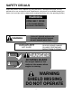
SAFETY DECALS Keep safety decals clean. Replace any safety decal that is damaged, destroyed, missing, painted over or can no longer be read. Replacement safety decals are available through your dealer. (Left and right sides are determined standing behind the unit in the operating position.) WARNING OPEN BELT DRIVE STOP ENGINE BEFORE REACHING UNDERNEATH WARNING - TURN OFF ENGINE AND ALLOW TO COOL BEFORE REFUELING. - DO NOT SMOKE NEAR FUEL.
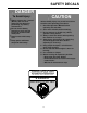
SAFETY DECALS DANGER CAUTION To Avoid Injury: • Always connect the “ground” (Black) cable last and remove it first whenever performing any battery maintenance. not contact battery • Do terminals or tools used to loosen the terminals with metal parts. contact with battery • Avoid acid. sparks and flames • Keep away from the battery. Serious bodily injury may result from failure to follow safe operating procedures. 1. Read the Operators Manual before operating this machine. 2.
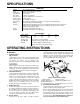
SPECIFICATIONS Engine: Type: Air Cleaner: Lube System: Fuel Tank: Transmission: Traction Drive: Ground Speed: Drive Wheels: Brakes: Controls: Frame Handles POWER UNIT 13 or 15 HP Kawasaki. 4-cycle, single-cylinder, recoil start. Dual element, dry-type. Pressurized. 5 gallons, polyethylene. 5 speeds forward and 1 speed reverse. Double V-belts. 2 to 4.5 MPH maximum. 13 x 6.50-6 pneumatic tires mounted on steel wheels with ball bearings. Two 6-inch drum, external band type.
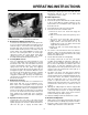
OPERATING INSTRUCTIONS Releasing the operator presence levers with either the transmission shift lever in gear or the blade clutch engaged will shut off the engine. B. Initial Adjustments 1. Disconnect the spark plug wire. 2. Check the tire pressure. Drive Wheels should be inflated to 25 psi. Caster Wheels should be inflated to 15 psi. Note: New tires are overinflated in order to properly seat the bead to the rim. 3. Check that all nuts, bolts and screws are tight. 4.
OPERATING INSTRUCTIONS 3. Move the mower outdoors. Check the engine gasoline level. When filling the tank, stop when the gasoline reaches one inch from the top. This space must be left for expansion. Use fresh, clean, unleaded, regular gasoline. 4. Move the mower to a “test area” where you can operate the mower for about half an hour without being disturbed. 5. To start the engine: a. Shift the transmission to neutral. b. Disengage the blade clutch. c.
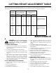
CUTTING HEIGHT ADJUSTMENT TABLE Note: The front edge of the cutting deck should be 1/8” - 1/4” below the rear edge of the deck so that the blades are cutting grass in only the front half of their circular path. This decreases friction and reduces the drive power required.
MAINTENANCE D. LUBRICATION CHART: See Figures 3, 4 & 5 for Item Location NUMBER OF GREASING POSITIONS ITEM DESCRIPTION 32” & 36” 48” & 52” DAILY 2 3 A Cutter Blade Spindle Bearings EVERY 40 HOURS 2 2 1 2 2 1 2 2 2 2 2 2 1 2 B C D E F G H Caster Wheel Bearing Caster Wheel Pivot Shafts Deck Idler Pulley Pivot Arms Drive Wheel Bearings Brake Lever Pivots Blade Clutch Bellcrank Pivot Transmission-Jackshaft Couplers Figure 3 E.
MAINTENANCE Figure 6 Figure 7 d. Slip the long blade drive belt off of the pulleys. e. (48" ONLY) Loosen the idler pull rod which holds the idler pulley tight against the short blade drive belt. (Item K, Figure 8.) f. Remove the short blade drive belt from the pulleys. g. Place a new short blade drive belt back on the pulleys and tighten the idler pull rod to hold the idler pulley tight against the belt. h.
MAINTENANCE 7. TO ADJUST THE LITE-TOUCH (MANUALLY) a.rThree holes in the belt guard allow you to reposition the hex cap screw to adjust the brake lever. The top hole (lite tension), the middle hole (medium tension) and the lower hole (hard tension). The unit is shipped with the hex screw in the top hole. SEE THE FIGURE BELOW FOR REFERENCE. To adjust the bolt do the following: b.With a spring puller, pull the spring and detach it from the hex cap screw. c.
MAINTENANCE SUGGESTED MOWER REPLACEMENT PARTS PART # 00021871 00050125 01007591 00011807 00021924 01007578 00050441 00021947 00050480 01000194 01000151 Description Rotary Blade, 16-1/2" Rotary Blade, 18" Blade Bolt Blade Nut Blade Spacer Drive Belt Drive Belt Long Drive Belt Short Drive Belt Transmission Drive Belt Traction Drive Belt 32" 2 36" 48" 3 2 2 2 10 2 2 10 1 3 3 15 1 1 2 1 1 1 2 1 2 SUGGESTED ENGINE REPLACEMENT PARTS Engine 01007290 Kawasaki, 13.0 HP 01009794 Kaw. Kai., 13.
Supplement Parking Instructions All Gear Walk-Behind Mowers INCORRECT Instructions 1. When parking mower on a hill, position mower perpendicular to the slope. DO NOT PARK MOWER FACING DOWN SLOPE. 2. Turn off the engine. 3. Place the Transmission Shift Lever in First Gear. 4. Disengage the Neutral Latch Levers. 5. Place chocks on both sides of the traction drive wheels. Alternate the chocks by placing one chock on the rear side of the wheel and another chock on the front side of the opposite wheel.
MAINTENANCE RECORD DATE WORK PERFORMED DATE 16 WORK PERFORMED
MAINTENANCE RECORD DATE WORK PERFORMED DATE 17 WORK PERFORMED
MAINTENANCE RECORD DATE WORK PERFORMED DATE 18 WORK PERFORMED
19
MANUFACTURER’S LIMITED WARRANTY - TURF EQUIPMENT This warranty is specific to the product manual to which it is attached. For a complete list of products and warranties contact your authorized Cub Cadet Commercial dealer. Proper maintenance of the purchased Cub Cadet Commercial equipment is the owner’s responsibility. Follow the instructions in your owner’s manual for correct lubricants and maintenance schedule.