Safe Operation Practices • Set-Up • Operation • Maintenance • Service • Troubleshooting • Warranty Operator’s Manual Self Propelled Mower — Model CC 550 SP WARNING READ AND FOLLOW ALL SAFETY RULES AND INSTRUCTIONS IN THIS MANUAL BEFORE ATTEMPTING TO OPERATE THIS MACHINE. FAILURE TO COMPLY WITH THESE INSTRUCTIONS MAY RESULT IN PERSONAL INJURY. CUB CADET LLC, P.O. BOX 361131 CLEVELAND, OHIO 44136-0019 Printed In USA Form No.
1 To The Owner Thank You Thank you for purchasing a Lawn Mower manufactured by Cub Cadet. It was carefully engineered to provide excellent performance when properly operated and maintained. If applicable, the power testing information used to establish the power rating of the engine equipped on this machine can be found at www.opei.org or the engine manufacturer’s web site. Please read this entire manual prior to operating the equipment.
Important Safe Operation Practices 2 WARNING: This symbol points out important safety instructions which, if not followed, could endanger the personal safety and/or property of yourself and others. Read and follow all instructions in this manual before attempting to operate this machine. Failure to comply with these instructions may result in personal injury. When you see this symbol.
12. A missing or damaged discharge cover can cause blade contact or thrown object injuries. 13. Many injuries occur as a result of the mower being pulled over the foot during a fall caused by slipping or tripping. Do not hold on to the mower if you are falling; release the handle immediately. 14. a. Step back from mower to fully extend your arms. b. Be sure you are well balanced with sure footing. c. Pull the mower back slowly, no more than half way toward you. d. Repeat these steps as needed.
Service 3. Check the blade and engine mounting bolts at frequent intervals for proper tightness. Also, visually inspect blade for damage (e.g., bent, cracked, worn) Replace blade with the original equipment manufacture’s (O.E.M.) blade only, listed in this manual. “Use of parts which do not meet the original equipment specifications may lead to improper performance and compromise safety!” 4. Mower blades are sharp and can cut. Wrap the blade or wear gloves, and use extra caution when servicing them.
Notice Regarding Emissions Engines which are certified to comply with California and federal EPA emission regulations for SORE (Small Off Road Equipment) are certified to operate on regular unleaded gasoline, and may include the following emission control systems: Engine Modification (EM), Oxidizing Catalyst (OC), Secondary Air Injection (SAI) and Three Way Catalyst (TWC) if so equipped.
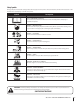
Safety Symbols This page depicts and describes safety symbols that may appear on this product. Read, understand, and follow all instructions on the machine before attempting to assemble and operate. Symbol Description READ THE OPERATOR’S MANUAL(S) Read, understand, and follow all instructions in the manual(s) before attempting to assemble and operate DANGER — ROTATING BLADES To reduce the risk of injury, keep hands and feet away.
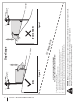
Section 2 — Important Safe Operation Practices Figure 1 line Figure 2 (TOO STEEP) 15° Slope WARNING! Slopes are a major factor related to tip-over and roll-over accidents which can result in severe injury or death. Do not operate machine on slopes in excess of 15 degrees. All slopes require extra caution. Always mow across the face of slopes, never up and down slopes. To check the slope, proceed as follows: 1. Remove this page and fold along the dashed line. 2.
3 Assembly & Set-Up Contents of Carton • One Lawn Mower • • One Lawn Mower Operator’s Manual • One Grass Catcher • One Side Discharge Chute One Engine Operator’s Manual • One Bottle of Oil Assembly NOTE: This unit is shipped without gasoline or oil in the engine. Fill up gasoline and oil as instructed in the Engine Operation section of this manual BEFORE operating your mower. Handle 1. Remove any packing material which may be between upper and lower handles. a.
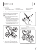
4. a. Hold blade control against upper handle. b. Pull starter rope out of the engine. Release blade control handle. c. Slip starter rope into rope guide. d. Tighten wing nut. Insert post on cable ties into holes provided on the lower handle. Pull cable tie tight and trim excess. A Grass Catcher 1. Follow steps below to assemble the grass catcher (if needed). Make certain bag is turned right side out before assembling (warning label will be on the outside). a.
Side Discharge Chute Adjustments To convert to side discharge, make sure grass catcher is off of the unit, the rear mulch plug is removed, and rear discharge door is closed. Cutting Height 1. On the side of the mower, lift the mulching plug. 2. Slide chute hooks under hinge pin on mulching plug assembly. Lower mulching plug. See Fig. 3-7. Do not remove side mulching plug at any time, even when you are not mulching. 1. The cutting height adjustment lever is located above the rear left wheel.
4 Controls and Features Drive Control Blade Control Recoil Starter Cutting Height Adjustment Lever Side Discharge Chute Mulch Plug Figure 4-1 Blade Control Recoil Starter The blade control is attached to the upper handle of the mower. Depress and squeeze it against the upper handle to operate the unit. Release it to stop engine and blade. The recoil starter is attached to the right upper handle. Stand behind the unit and pull the recoil starter rope to start the unit.
5 Operation Starting Engine WARNING: Be sure no one other than the operator is standing near the lawn mower while starting engine or operating mower. Never run engine indoors or in enclosed, poorly ventilated areas. Engine exhaust contains carbon monoxide, an odorless and deadly gas. Keep hands, feet, hair and loose clothing away from any moving parts on engine and lawn mower. 1. Standing behind the mower, squeeze and hold the blade control against upper handle. 2.
6 Maintenance & Adjustments Maintenance 4. General Recommendations The transmission is pre-lubricated and sealed at the factory and does not require lubrication. 5. Follow the Maintenance section in the engine manual for lubrication schedule and instruction for engine lubrication. • Always observe safety rules when performing any maintenance. • The warranty on this lawn mower does not cover items that have been subjected to operator abuse or negligence.
Replacing Rear Flap Adjustments 1. To remove rear flap, lift rear door, and remove screw on either side to remove from hole. See Fig. 6-2. Drive Cable 2. Remove screw and flap from opposite hole and replace with new flap in the opposite order and manner of removal. Your unit is equipped with an adjustable drive cable to adjust the tension on the drive cable.
7 Service Blade Care 5. Periodically inspect the blade adapter for cracks, especially if you strike a foreign object. Replace when necessary. Follow the steps below for blade service. Lubricate the engine crankshaft and the inner surface of the blade adapter with light oil. Slide the blade adapter onto the engine crankshaft. Place the blade on the adapter such that the side of the blade marked “Bottom” (or with part number) faces the ground when the mower is in the operating position.
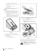
c. Working from the rear of the mower, carefully remove belt from transmission pulley. See Fig. 7-3. d. Once belt is off transmission pulley, push down on deck baffle to access engine pulley and slide belt off this pulley and out from under the deck. See Fig. 7-3. C D Off-Season Storage The following steps should be taken to prepare your lawn mower for storage. • Clean and lubricate mower thoroughly as described in the lubrication instructions.
8 Troubleshooting Problem Engine Fails to start Cause Remedy 1. Blade control disengaged. 1. Engage blade control. 2. Spark plug boot disconnected. 2. Connect wire to spark boot. 3. Fuel tank empty or stale fuel. 3. Fill tank with clean, fresh gasoline. 4. Engine not primed (if equipped with primer). 4. Prime engine as instructed in the Operation section. 5. Faulty spark plug. 5. Clean, adjust gap, or replace. 6. Blocked fuel line. 6. Clean fuel line. 7. Engine flooded. 7.
Problem Uneven cut Mower will not self propel Cause Remedy 1. Wheels not positioned correctly. 1. Place all four wheels in same height position (if equipped with individual height adjusters). 2. Dull blade. 2. Sharpen or replace blade. 1. Belt not installed properly. 1. Check belt for proper pulley installation and movement. 2. Debris clogging drive operation. 2. Stop engine, disconnect spark plug boot, and clean out debris. 3. Damaged or worn belt. 3. Inspect and replace belt.
9 Replacement Parts & Accessories Component Part Number and Description 951-10292 Spark Plug 951-10298 Air Cleaner Kit 951-10300 Fuel Cap Assembly 951-10358A Fuel Filter 634-04346 934-04348 Wheel (Front) Wheel (Rear) 731-04177 Side Discharge Chute 964-04066 Grass Bag Phone (877) 282-8684 for your nearest Cub Cadet Dealer to order replacement parts or a complete Parts Manual (have your full model number and serial number ready). Parts Manual downloads are also available free of charge at www.
Component Part Number and Description 942-0739 Mulching Blade 954-04158 Accessories V-Belt 490-850-0005 490-850-0008 Blade Removal Tool Oil Siphon Phone (877) 282-8684 for your nearest Cub Cadet Dealer to order replacement parts or a complete Parts Manual (have your full model number and serial number ready). Parts Manual downloads are also available free of charge at www.cubcadet.com.
CUB CADET LLC MANUFACTURER’S LIMITED WARRANTY FOR WALK-BEHIND MOWERS IMPORTANT: To obtain warranty coverage owner must present an original proof of purchase and applicable maintenance records to the servicing dealer. Please see the operator’s manual for information on required maintenance and service intervals.