Safe Operation Practices • Set-Up • Operation • Maintenance • Service • Troubleshooting • Warranty Operator’s Manual RZT L Series Tractor WARNING READ AND FOLLOW ALL SAFETY RULES AND INSTRUCTIONS IN THIS MANUAL BEFORE ATTEMPTING TO OPERATE THIS MACHINE. FAILURE TO COMPLY WITH THESE INSTRUCTIONS MAY RESULT IN PERSONAL INJURY. CUB CADET LLC, P.O. BOX 361131 CLEVELAND, OHIO 44136-0019 Printed In USA Form No.
1 To The Owner Thank You Thank you for purchasing a Cub Cadet Zero-Turn Tractor. It was carefully engineered to provide excellent performance when properly operated and maintained. If applicable, the power testing information used to establish the power rating of the engine equipped on this machine can be found at www.opei.org or the engine manufacturer’s web site. Please read this entire manual prior to operating the equipment.
Important Safe Operation Practices 2 WARNING! This symbol points out important safety instructions which, if not followed, could endanger the personal safety and/or property of yourself and others. Read and follow all instructions in this manual before attempting to operate this machine. Failure to comply with these instructions may result in personal injury. When you see this symbol.
12. A missing or damaged discharge cover can cause blade contact or thrown object injuries. 13. Stop the blade(s) when crossing gravel drives, walks, or roads and while not cutting grass. 14. Watch for traffic when operating near or crossing roadways. This machine is not intended for use on any public roadway. 15. Do not operate the machine while under the influence of alcohol or drugs. 16. Mow only in daylight or good artificial light. 17. Never carry passengers. 18. Back up slowly.
Children a. Use only an approved gasoline container. 1. b. Never fill containers inside a vehicle or on a truck or trailer bed with a plastic liner. Always place containers on the ground away from your vehicle before filling. c. When practical, remove gas-powered equipment from the truck or trailer and refuel it on the ground. If this is not possible, then refuel such equipment on a trailer with a portable container, rather than from a gasoline dispenser nozzle. d.
Check the blade(s) and engine mounting bolts at frequent intervals for proper tightness. Also, visually inspect blade(s) for damage (e.g., excessive wear, bent, cracked). Replace the blade(s) with the original equipment manufacturer’s (O.E.M.) blade(s) only, listed in this manual. “Use of parts which do not meet the original equipment specifications may lead to improper performance and compromise safety!” Do not modify engine 6. Mower blades are sharp.
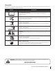
Safety Symbols This page depicts and describes safety symbols that may appear on this product. Read, understand, and follow all instructions on the machine before attempting to assemble and operate. Symbol Description READ THE OPERATOR’S MANUAL(S) Read, understand, and follow all instructions in the manual(s) before attempting to assemble and operate WARNING— ROTATING BLADES Do not put hands or feet near rotating parts or under the cutting deck. Contact with the blade(s) can amputate hands and feet.
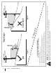
Section 2 — Safe Operation Practices Figure 1 line Figure 2 (TOO STEEP) 15° Slope WARNING! Slopes are a major factor related to tip-over and roll-over accidents which can result in severe injury or death. Do not operate machine on slopes in excess of 15 degrees. All slopes require extra caution. Always mow across the face of slopes, never up and down slopes. To check the slope, proceed as follows: 1. Remove this page and fold along the dashed line. 2.
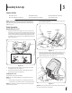
3 Assembly & Set-Up Contents of Crate • One RZT L Tractor • One Oil Drain Tube • One Deck Wash Hose Coupler • One Tractor Operator’s Manual • One Engine Operator’s Manual • One Hardware Pack NOTE: This Operator’s Manual covers several models. Tractor features may vary by model. Not all features in this manual are applicable to all tractor models and the tractor depicted may differ from yours. 2. Remove the two shoulder screws and lock nuts in the seat pan as shown in Figure 3-2.
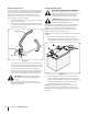
Position Drive Control levers Connecting the Battery Cables CALIFORNIA PROPOSITION 65 WARNING! Battery posts, terminals, and related accessories contain lead and lead compounds, chemicals known to the State of California to cause cancer and reproductive harm. Wash hands after handling. The drive control levers of the tractor are lowered for shipping purposes. The hex screws and flat washers that normally secure the control levers in their operating position are in a hardware pack inside your manual bag.
Lower Deck Discharge Chute Deflector Adjusting the Seat WARNING! Never operate the mower deck without the chute deflector installed and in the down position. To adjust the position of the seat, pull up and hold the seat adjustment lever. Slide the seat forward or rearward to the desired position; then release the adjustment lever. Make sure seat is locked into position before operating the tractor. See Figure 3-8. The discharge chute deflector must be installed before operating the mower. 1.
4 Controls & Features Deck Lift Handle LH Drive RH Drive Control Lever Control Lever Seat Adjustment Lever Deck Height Index Throttle Control or Throttle/Choke Control Hour Meter/ Indicator Panel Choke Control PTO Switch Ignition Switch Fuel Level Window Fuel Tank Cap Cup Holder Storage Tray LH Transmission Bypass Rod NOTE: This Operator’s Manual covers several models. Tractor features may vary by model.
Ignition Switch Fuel Tank Cap The ignition switch is located on the RH console to the rear of the PTO switch. The ignition switch has three positions as follows: The fuel tank cap is located near the middle of the LH console. Turn the fill cap approximately 1⁄4 turn and pull upward to remove. The fuel cap is tethered to the tractor to prevent its loss. Do not attempt to remove the cap from the tractor. Fill tank to the bottom of the filler neck, allowing some space in the tank for fuel expansion.
Throttle Control (If so equipped) Indicator Panel Features The throttle control is located on the RH console to the left of the hour meter/indicator panel. When set in a given position, a uniform engine speed will be maintained. FAST Illuminates and the battery voltage is displayed briefly when the ignition switch it turned to the “ON” position. Push the throttle control handle forward to increase the engine speed.
5 Operation General Safety • • • RECEIVE INSTRUCTION — Entirely read this operator’s manual. Learn to operate this machine SAFELY. Do not risk INJURY or DEATH. Allow only those who have become competent in its usage to operate this tractor. Before starting the engine or beginning operation, be familiar with the controls. The operator should be in the operator’s seat. The PTO switch must be in the disengaged position and the RH and LH drive control levers moved fully outward in the neutral position.
Starting the Engine WARNING! This tractor is equipped with a safety interlock system designed for the protection of the operator. Do not operate the tractor if any part of the interlock system is malfunctioning. Periodically check the functions of the interlock system for proper operation. WARNING! For personal safety, the operator must be sitting in the tractor seat when starting the engine. 1.
Practice Operation (Initial Use) 3. Operating a zero-turn tractor is not like operating a conventional type riding tractor. Although and because a zero turn tractor is more maneuverable, getting used to operating the control levers takes some practice. NOTE: Although the tractor’s engine is designed to run at full throttle, when performing a practice session the tractor must be operated at less than full throttle. This only applies to practice.
Turning the Tractor While Driving Forward WARNING! When reversing the direction of travel, we recommend performing gradual ‘U’ turns where possible. Sharper turns increase the possibility of turf defacement, and could affect control of the tractor. ALWAYS slow the tractor before making sharp turns. To turn the tractor while driving forward, move the control levers as necessary so that one lever is rearward of the other. The tractor will turn in the direction of the rearward control lever. 1.
Turning While Driving Rearward Executing a Zero Turn WARNING! When executing a zero turn, the tractor To turn the tractor while driving rearward, move the control levers as necessary so that one lever is forward of the other. The tractor will turn in the direction of the forward control lever. 1. To turn to the left while traveling in reverse, move the left drive control lever forward of the right lever. See Fig. 5-7. MUST BE STOPPED.
Stopping the Tractor 1. Move both drive control levers to the neutral position to stop the motion of the tractor. 2. Push the PTO switch downward to the disengaged position. 3. Use the deck lift handle to raise the deck to its highest position. 4. If dismounting the tractor, move the drive control handles fully outward in the neutral position which also engages the parking brake, move the throttle control lever to the fast position, turn the ignition switch to stop and remove the key from the switch.
Checking the Safety Interlock Circuits Periodically check the safety interlock circuits to ensure they are working properly. If a safety circuit is not working as designed, contact you Cub Cadet dealer to have the tractor inspected. DO NOT operate the tractor if any safety circuit is not functioning properly. To check the safety circuits, proceed as follows: 1. Pull the PTO switch upward to the engaged position. Momentarily turn the ignition switch to the start position; the engine should not crank. 2.
6 Maintenance & Adjustments Maintenance Schedule Before Each use Check Engine Intake Screen/Cover Every 10 Hours Every 25 Hours Every 50 Hours Every 100 Hours Prior to Storing P Clean Battery Terminals Lube Front Wheels P P P P Clean Engine Cooling Fins Lube Front Deck Wheels NOTE: This Operator’s Manual covers several models. Tractor features may vary by model. Not all features in this manual are applicable to all tractor models and the tractor depicted may differ from yours. P P P P 3.
Tires 4. Check the tire air pressure after every 50 hours of operation or weekly. Keep the tires inflated to the recommended pressures. Improper inflation will shorten the tire service life. See the tire side wall for proper inflation pressures. Observe the following guidelines: • Do not inflate a tire above the maximum pressure shown on the sidewall of the tire. • Do not reinflate a tire that has been run flat or seriously under inflated. Have it inspected and serviced by a qualified tire mechanic.
Tractor Storage Removing The Tractor From Storage If your tractor is not going to be operated for an extended period of time (thirty days to approximately six months), the tractor should be prepared for storage. Store the tractor in a dry and protected location. If stored outside, cover the tractor (including the tires) to protect it from the elements. The procedures outlined below should be performed whenever the tractor is placed in storage. 1. Check the engine oil. 2.
To adjust the drive control levers forward/rearward, proceed as follows: 4. 1. The deck is properly leveled when both blade tip measurements are equal. Retighten the hex bolt on the front left deck hanger bracket when proper adjustment is achieved. If not already loose, loosen the hex screw and rotate the control lever either forward or rearward to the desired position. See Figure 6-3. NOTE: If the control lever is too tight to move, slightly loosen the hex crew at the bottom of the control lever. 2.
Adjusting the Front Gauge Wheels Adjusting the Rear Deck Rollers (If so equipped) WARNING!: Keep hands and feet away from the discharge opening of the cutting deck. The front gauge wheels on the mower deck are an anti-scalp feature, and should not ride on the ground. The front gauge wheels should be approximately 1⁄4-1⁄2” above the ground when the deck is set in the desired height setting. The rear deck rollers can be set in either the low or high position.
Off-Season Storage Removing the Riding Mower from Storage Riding Mower Storage 1. Check the engine oil. 2. Fully charge the battery, lower riding mower off blocks, and inflate the tires to the recommended pressure. 3. Remove the spark plugs and wipe them off. Using the starter, crank the engine to pump the excess oil out of the spark plug holes. Replace the spark plugs and the ignition leads. 4. If drained before storing, fill the fuel tank with clean, fresh gasoline. 5.
7 Service Battery Removal Charging the Battery WARNING! Battery posts, terminals and related accessories contain lead and lead compounds. Wash hands after handling. Test and, if necessary, recharge the battery after the tractor has been stored for a period of time. • The battery is located beneath the seat frame. To remove the battery: 1. Remove the hex washer screw securing the battery holddown bracket to the frame. Then flip the battery holddown bracket up to free the battery. See Figure 7-1.
Releasing Belt Tension with the Idler Pulley Rolling the Belt off the PTO Pulley 1. 1. Using the deck lift handle, raise the deck to the position that provides the most horizontal run of the belt between the deck idler pulleys and the PTO pulley on the bottom of the engine. 2. Sitting behind the tractor facing forward, reach beneath the tractor to grasp the belt at the front of the PTO pulley.
6. Pull the cotter pin out of the front deck lift rod securing it to the deck. See Figure 7-6. Slide the deck lift rod out of the front hanger bracket. Deck Installation Install the deck on the tractor as follows: 1. Place the deck lift handle in the highest mowing position See Figure 7-3. 2. Slide the deck under the tractor on the right side of the tractor lining up the deck hanger brackets and the deck lift arms.. 3.
Replacing the Belt 6. Place the belt around the idler pulleys removed in step 3 with the “V” side facing in. Once in place, reinstall all the hardware and tighten the flange lock nut to secure the assembly. See Figure 7-8. Route the belt as shown in Figure 7-8 and then reinstall the deck (refer to Deck Installation on page 30). 42” Deck 1. Remove the deck from beneath the tractor, (refer to Deck Removal on page 28). 7. 2. Remove the hex washer screws securing the belt covers to the deck.
4. Remove the belt from the spindle pulleys. 5. Install the new belt around the spindle pulleys as shown and reinstall the belt covers. See Figure 7-9. 6. Place the belt around the idler pulleys removed in step 3 with the “V” side facing in. Once in place, reinstall all the hardware and tighten the flange lock nut to secure the assembly. See Figure 7-10. 7. 3. Remove the two idler pulleys by removing the hex screws and flange lock nuts that secure them to the deck and the idler arm. See Figure 7-12.
Mower Blade Care Changing the Transmission Drive Belt WARNING! Before performing any maintenance, place the PTO switch in the “OFF” position, engage the parking brake lever, turn the ignition key to the “OFF” position and remove the key from the switch. Protect your hands by using heavy gloves when handling the blades. When servicing the mower deck, be careful not to cut yourself on the sharpened blades. The cutting blades must be kept sharp at all times.
8 Troubleshooting Problem Excessive vibration Uneven cut Mower will not mulch grass (If Equipped w/Mulching Kit) 34 Cause Remedy 1. Cutting blade loose or unbalanced. 1. Tighten blade and spindle. 2. Damaged or bent cutting blade. 2. Replace blade. 1. Deck not leveled properly. 1. Perform side-to-side deck adjustment. 2. Dull blade. 2. Sharpen or replace blade. 3. Uneven tire pressure. 3. Check tire pressure in all four tires. 1. Engine speed too low. 1.
9 Replacement Parts Component Part Number and Description 954-04033A 954-05008 954-04329 Deck Belt, RZT L42 Deck Belt, RZT L50 Deck Belt, RZT L54 954-04317 Drive Belt 942-04312 942-04053C 942-04053C-X 942-0677B 942-0677-X Deck Blade, RZT L42 Deck Blade, RZT L50 Extreme Blade, RZT L50 Deck Blade, RZT L54 Extreme Blade, RZT L54 918-04822A 918-04125B 918-05137 Deck Spindle, RZT L42 Deck Spindle, RZT L50 Deck Spindle, RZT L54 734-04155 Deck Wheel 925-1707D Battery 951-12428 Fuel Tank Cap Phone
Component Part Number and Description 946-04214 Choke Control Cable (w/ Kawasaki) 946-04352A 946-4830A Throttle Control Cable (w/ Kawasaki) Throttle/Choke Control Cable (w/ Kohler) 925-1744A Ignition Key 631-04288 631-05058 Discharge Chute Assy., RZT L42 Discharge Chute Assy., RZT L50 & RZT L54 634-04293-0931 Wheel Assembly, RZT L42 634-04128-0931 Wheel Assembly, RZT L50 & RZT L54 634-04212B 634-04711 Caster Wheel Assy., RZT L42 Caster Wheel Assy.
10 Attachments & Accessories The following attachments and accessories are compatible with your Cub Cadet RZT L tractor. See your Cub Cadet dealer or the retailer from which you purchased your tractor for information regarding price and availability.
FEDERAL and/or CALIFORNIA EMISSION CONTROL WARRANTY STATEMENT YOUR WARRANTY RIGHTS AND OBLIGATIONS MTD Consumer Group Inc, the United States Environmental Protection Agency (EPA), and, for those products certified for sale in the state of California, the California Air Resources Board (CARB) are pleased to explain the emission (evaporative and/or exhaust) control system (ECS) warranty on your outdoor 2006 and later small off-road spark-ignited engine and equipment (outdoor equipment engine) In California, n
10. Add-on or modified parts that are not exempted by the Air Resources Board may not be used. The use of any non-exempted add-on or modified parts by the ultimate purchaser will be grounds for disallowing a warranty claims. MTD Consumer Group Inc will not be liable to warrant failures of warranted parts caused by the use of a non-exempted add-on or modified part.
CUB CADET LLC MANUFACTURER’S LIMITED WARRANTY FOR RESIDENTIAL ZERO-TURN (“RZT”) MOWERS IMPORTANT: To obtain warranty coverage owner must present an original proof of purchase and applicable maintenance records to the servicing dealer. Please see the operator’s manual for information on required maintenance and service intervals.
Medidas importantes de seguridad • Configuración • Funcionamiento • Mantenimiento • Servicio • Solu Manual del Operador Tractor Serie RZT L ADVERTENCIA LEA Y RESPETE TODAS LAS NORMAS DE SEGURIDAD E INSTRUCCIONES INCLUIDAS EN ESTE MANUAL ANTES DE PONER EN FUNCIONAMIENTO ESTA MÁQUINA. SI NO RESPETA ESTAS INSTRUCCIONES PUEDE PROVOCAR LESIONES PERSONALES. CUB CADET LLC, P.O. BOX 361131 CLEVELAND, OHIO 44136-0019 Impreso en Estados Unidos de América Formulario No.
1 Al propietario Gracias Gracias por comprar una Cub Cadet cero a su vez de tractores. La misma ha sido diseñada cuidadosamente para brindar excelente rendimiento si se la opera y mantiene correctamente. Por favor lea todo este manual antes de operar el equipo. Le indica cómo configurar, operar y mantener la máquina con seguridad y fácilmente.
2 Medidas importantes de seguridad ADVERTENCIA: La presencia de este símbolo indica que se trata de instrucciones importantes de seguridad que se deben respetar para evitar poner en peligro su seguridad personal y/o material y la de otras personas. Lea y siga todas las instrucciones de este manual antes de poner en funcionamiento esta máquina. Si no respeta estas instrucciones puede provocar lesiones personales. Cuando vea este símbolo.
4 10. Esté atento a la cortadora y a la dirección de la descarga de los aditamentos y no apunte a nadie. Nunca haga funcionar la cortadora de césped sin que estén colocados la cubierta de descarga o todo el colector de recortes de césped. 25. Desenganche todos los embragues de los accesorios, coloque el freno de mano en posición ‘on’ y mueva las palancas de control de transmisión totalmente hacia afuera a la posición neutral antes de intentar arrancar la máquina. 11.
6. Haga que todos los movimientos en las pendientes sean lentos y graduales. No cambie repentinamente la velocidad ni la dirección. La aceleración o la reducción repentina de velocidad puede hacer que el frente de la máquina se levante y dé una voltereta hacia atrás, lo que podría producir lesiones graves. 2. No permita nunca que los niños menores de 14 años utilicen esta máquina.
Llene el tanque no más de ½ pulgada por debajo de la base del cuello del tapón de carga, para dejar espacio para la expansión del combustible. 8. Nunca modifique el sistema de bloqueo de seguridad ni otros mecanismos de seguridad. Controle periódicamente que funcionen correctamente. i. Vuelva a colocar la tapa de la gasolina y ajústela bien. 9. j. Limpie el combustible que se haya derramado sobre el motor y el equipo. Traslade la máquina a otra zona. Espere 5 minutos antes de encender el motor.
Amortiguador de chispas ADVERTENCIA: Esta máquina está equipada con un motor de combustión interno y no debe ser utilizada en o cerca de un terreno agreste cubierto por bosque, malezas o hierba excepto que el sistema de escape del motor esté equipado con un amortiguador de chispas que cumpla con las leyes locales o estatales correspondientes (en caso de existir). Si se utiliza un amortiguador de chispas el operador lo debe mantener en condiciones de uso adecuadas.
8 Sección 2 — Medidas importantes de seguridad Figura 1 tinua iscon nea d 15° lí 15° Pendiente ADVERTENCIA! Las pendientes son un factor importante relacionado con un vuelco y renovación de los accidentes que pueden provocar lesiones graves o la muerte. No utilice la máquina en pendientes de más de 15 grados. Todos pendientes requiere mayor precaución. Si no puede retroceder en la pendiente o si se siente inseguro en ella, no la recorte. Siempre corte el césped en toda la superficie de la cuesta.
3 Montaje y Configuración Contenido del cajón • Un tractor corta césped • Un tubo de drenaje de aceite • Un Manual del operador del tractor RZT Manual • Un Manual del operador del motor NOTA: Este Manual abarca varios modelos. características del tractor pueden variar según el modelo. No todas las características de este manual son aplicables a todos los modelos de tractor y el tractor se muestra puede ser diferente de la suya. 2.
Posición palancas de control Conexión de los cables de la batería Las palancas de control del tractor se bajan para el embarque. Los tornillos hexagonales y las arandelas planas que normalmente fijan las palancas de control en su posición de trabajo se encuentran en un paquete de hardware dentro de su bolsa manual. Las palancas de control debe ser reposicionado para operar el tractor.
Baje el deflector del canal de descarga de la plataforma ¡ADVERTENCIA! Nunca opere la plataforma de la cortadora sin el deflector de descarga instalado y en posición baja. Se debe instalar el deflector del canal de descarga antes de operar la cortadora de césped. 1. Retire las chavetas que están sujetas con una unión con cierre al soporte del canal. 2. Retire las tuercas de seguridad con brida de la plataforma.
4 Controles y Características Manija de elevación de la plataforma Posicionamiento de la altura de la plataforma Palanca de ajuste del asiento Palanca de control de transmisión izquierda Palanca de control de transmisión derecha Indicador de nivel de combustible Tapón del tanque de combustible Control del regulador o Del acelerador y del estrangulador Medidor horario/ Panel indicador Estrangulador Interruptor de potencia de arranque Interruptor de encendido Portacubeta Bandeja de almacenamiento LH
Interruptor de encendido Tapón del tanque de combustible El interruptor de encendido está ubicado en la consola del lado derecho, a la derecha del asiento del operador. El interruptor de encendido tiene tres posiciones. El tapón del depósito de combustible está ubicado cerca de la parte media de la consola del lado izquierdo. Gire el tapón aproximadamente 1⁄4 de vuelta y tire hacia arriba para extraerlo. El tapón del combustible está amarrado al tractor para impedir que se pierda.
Control del regulador (Si lo tiene) Características del panel indicador El control del regulador está ubicado en la consola del lado izquierdo, a la izquierda del asiento del operador. Cuando se lo coloca en cierta posición, se mantiene una velocidad de motor uniforme. FAST Empuje la manija de control del regulador hacia adelante para aumentar la velocidad del motor.
5 Funcionamiento Seguridad general • • RECIBA LAS INSTRUCCIONES - Lea este manual del operador en su totalidad. Aprenda a operar esta máquina CON SEGURIDAD. No se arriesgue a quedar expuesto a LESIONES o a la MUERTE. Solamente se debe permitir operar este tractor a quienes se hayan familiarizado a fondo con el uso del mismo. Antes de arrancar el motor o de empezar a operar, familiarícese con los controles. El operador debe estar en el asiento del operador.
Encendido del motor ¡ADVERTENCIA!: Esta unidad está equipada con un sistema de bloqueo de seguridad para protección del operador. No opere el tractor si alguna parte del sistema de bloqueo funciona mal. Controle periódicamente las funciones del sistema de bloqueo para verificar que funcionen adecuadamente. 6. 7. 8. ¡ADVERTENCIA!: Por razones de seguridad personal, el operador debe estar sentado en el asiento del tractor al arrancar el motor. 1.
Practique el modo de operación con el tractor (uso inicial) 4. Operar un tractor con radio de giro cero no es lo mismo que operar un tractor convencional. Si bien precisamente un tractor con radio de giro cero es más maniobrable, es necesario practicar la operación de las palancas de control para acostumbrarse a las mismas. NOTA: Si bien el motor del tractor se ha diseñado para funcionar a máxima aceleración, cuando practica el tractor debe funcionar a menos del máximo (aproximadamente 2500-3000 RPM).
Giro con el tractor en marcha directa ¡ADVERTENCIA! Al invertir la dirección del recorrido, le recomendamos que en lo posible realice giros graduales en "U". Los giros más agudos aumentan la posibilidad de que se deteriore el césped y podrían afectar el control del tractor. Conduzca SIEMPRE el tractor lentamente antes de girar en curvas cerradas. Para que el tractor gire mientras se desplaza hacia adelante, mueva las palancas de control según sea necesario para que una palanca quede más atrás que la otra.
Realizar un giro mientras se conduce marcha atrás Para que el tractor gire mientras se desplaza hacia atrás, mueva las palancas de control según sea necesario para que una palanca quede más adelante que la otra. El tractor girará en la dirección de la palanca que queda más adelante. 1. Para girar a la izquierda mientras se desplaza marcha atrás, mueva la palanca de control del lado izquierdo hacia adelante respecto de la palanca derecha. Vea la Figura 5-7.
Detención del tractor 1. 2. 3. 4. Mueva las dos palancas de control a la posición neutral para detener el movimiento del tractor. Presione el interruptor de la potencia de arranque (PTO) hacia abajo a la posición desenganchada. Use la manija de elevación de la plataforma para levantar la plataforma a su posición más alta.
Control de los circuitos de bloqueo de seguridad Controle periódicamente los circuitos de bloqueo de seguridad para estar seguro de que funcionan adecuadamente. Si algún circuito de seguridad no funciona según diseño, póngase en contacto con el distribuidor Cub Cadet para que inspeccione el tractor. NO use el tractor si algún circuito de seguridad no está funcionando adecuadamente. Para controlar los circuitos de seguridad proceda de la siguiente manera: 1.
6 Mantenimiento y Ajustes Programa de mantenimiento Antes de cada uso Inspeccione la pantalla/cubierta de entrada del motor Cada 10 horas Cada 25 horas Cada 50 horas Cada 100 horas Antes de almacenar P Limpie los bornes de la batería Lubrique las ruedas delanteras P P P P Limpie las aletas de refrigeración del motor Lubrique las ruedas delanteras de la plataforma NOTA: Este manual de operación trata distintos modelos. Las características del tractor pueden variar según los modelos.
Neumáticos 4. Controle la presión de aire de los neumáticos cada 50 horas de operación o una vez por semana. Mantenga los neumáticos inflados a las presiones recomendadas. El inflado inadecuado de un neumático reduce su vida útil. Consulte los laterales de los neumáticos para averiguar las presiones de inflado adecuadas. Respete las siguientes pautas: Uso de las varillas de derivación de la transmisión • No infle los neumáticos por encima de la presión máxima que se muestra en el lateral del neumático.
Almacenamiento del tractor Retiro del tractor del lugar de almacenamiento Si el tractor no a va a funcionar por un período prolongado (desde treinta días hasta aproximadamente seis meses), se lo debe preparar para el almacenamiento. Guarde el tractor en un lugar seco y protegido. Si lo guarda afuera, cúbralo (incluidos los neumáticos) para protegerlo de los fenómenos climáticos. Cada vez que se prepara el tractor para dejarlo fuera de uso se deben realizar los procedimientos descriptos más abajo. 1.
Para ajustar las palancas de control hacia adelante o hacia atrás, proceda de la siguiente forma: 4. 1. La plataforma se encuentra correctamente nivelada cuando las dos mediciones desde las puntas de las cuchillas son iguales. Una vez alcanzado el ajuste necesario, vuelva a ajustar el perno de cabeza hexagonal de la ménsula del gancho delantero izquierdo de la plataforma. Afloje el tornillo hexagonal si aún no lo aflojaron y rote la palanca de control hacia adelante o hacia atrás a la posición deseada.
Ajuste de las ruedas de calibración delanteras ¡ADVERTENCIA! Mantenga las manos y pies alejados de la abertura de descarga de la plataforma de corte. Las ruedas calibradoras delanteras de la plataforma de la cortadora de césped constituyen un mecanismo para el cuidado del césped y no se deben usar para desplazarse sobre el piso.
8. Limpie y cargue completamente la batería, luego desconecte el cable negativo de la batería para evitar posibles descargas. Vuelva a cargar la batería periódicamente durante el almacenamiento. NOTA: Retire la batería si está expuesta a períodos prolongados de temperaturas bajo cero. Almacene en un lugar fresco y seco donde las temperaturas están por encima de la congelación. 9. Lubrique todos los puntos de lubricación. 10.
7 Servicio Retiro de la batería Carga de la batería ¡ADVERTENCIA! Los postes, bornes y accesorios de la batería contienen plomo y compuestos de plomo. Lávese las manos después de estar en contacto con estos componentes. Si el tractor ha estado guardado durante un tiempo, pruebe la batería y, si es necesario, recárguela. • La batería está ubicada debajo del marco del asiento. Para retirar la batería: 1.
Para aflojar la tensión de la correa con la polea loca. 1. Usando la manija de elevación de la plataforma, levante la plataforma a la posición que le ofrece mayor recorrido horizontal de la correa entre las poleas locas de la plataforma y la polea de la PTO en la base del motor. Vea la Figura 7-3. Haciendo rodar la correa para sacarla de la polea de la toma de fuerza (PTO). 1.
6. Tire del pasador de chaveta hacia afuera de la varilla de elevación delantera de la plataforma que la sujeta a la plataforma. Consulte la Figura 7-6. Deslice la varilla de elevación de la plataforma fuera de la ménsula de suspensión frontal. Instalación de la plataforma Instale la plataforma sobre el tractor de la siguiente forma: 1. Ubique la manija de elevación de la plataforma en la posición de corte más elevada. Vea la Figura 7-3. 2.
Cambio de la correa Cubierta 42” 1. Retire la plataforma desde abajo del tractor (consulte Retiro de la plataforma en la página 28). 2. 4. Retire la correa de las poleas del husillo. 5. Instale la nueva correa alrededor de las poleas del husillo tal como se muestra y reinstale las cubiertas de las correas. Consulte la Figura 7-8. 6. Coloque la correa alrededor de las poleas locas que extrajo en el paso 3 con el lado en “V” orientado hacia adentro.
3. Extraiga las dos poleas locas, para lo cual debe retirar los tornillos de cabeza hexagonal y las tuercas de seguridad con brida que las sujetan a la plataforma y el brazo de polea loca. Consulte la Figura 7-11. No afloje ningún elemento de ferretería al sacar el tornillo de cabeza hexagonal y la tuerca de seguridad con brida. Cubierta 50” y 54" 1. Retire la plataforma desde abajo del tractor (consulte Retiro de la plataforma en la página 28). 2.
Cuidado de las cuchillas de la cortadora de césped ¡ADVERTENCIA! Antes de realizar cualquier tarea de mantenimiento, coloque el interruptor de la toma de fuerza (PTO) en la posición "OFF" (apagado), enganche la palanca del freno de mano, gire la llave de encendido a la posición "OFF" (apagado) y retire la llave del interruptor. Proteja sus manos utilizando guantes reforzados cuando manipule las cuchillas.
8 Solución de Problemas Problema Vibración excesiva Corte desigual La cortadora de césped no procesa los recortes como abono (si está equipada con kit de abono) 34 Causa Solución 1. Cuchilla de corte floja o descentrada. 1. Apriete la cuchilla y el husillo. 2. Cuchilla dañada o curvada. 2. Reemplace la cuchilla. 1. La plataforma no está correctamente nivelada. 1. Haga un ajuste de la plataforma de lado a lado. 2. La cuchilla de la cortadora no está afilada. 2. Afile o cambie la cuchilla. 3.
Notas 9 35
36 Section 9 — Notas
Section 9 — Notas 37
DECLARACIÓN FEDERAL y/o DE CALIFORNIA SOBRE GARANTÍAS EN EL CONTROL DE EMISIONES SUS DERECHOS Y OBLIGACIONES EN CUANTO A LA GARANTÍA MTD Consumer Group Inc, la Agencia de Protección Medioambiental de los Estados Unidos (EPA), y para aquellos productos certificados para su venta en el estado de California, el Departamento de los Recursos del Aire de California (CARB) se complacen en explicar la garantía que cubre al sistema de control (ECS) de emisiones (evaporativas y/o de escape) de su equipo y motor (moto
8. Durante la totalidad del período de garantía del motor y equipo para todo terreno arriba mencionado, MTD Consumer Group Inc mantendrá un suministro de piezas bajo garantía suficiente para satisfacer la demanda esperada de tales piezas. 9. Cualquier pieza de reemplazo se podrá usar para el cumplimiento del mantenimiento o las reparaciones bajo garantía y se suministrarán sin cargo para el propietario. Dicho uso no reducirá las obligaciones de garantía de MTD Consumer Group Inc. 10.
GARANTÍA LIMITADA DEL FABRICANTE PARA CORTADORAS DE CÉSPED RESIDENCIALES DE RADIO DE GIRO CERO (“RZT”) IMPORTANTE: Para obtener cobertura de garantía, el propietario debe presentar una evidencia original de la compra y los registros de mantenimiento correspondientes al centro de servicio técnico autorizado del distribuidor. Consulte el manual del operador para obtener información sobre los intervalos de mantenimiento y servicio requeridos. LLC en P.O.