Safe Operation Practices • Set-Up • Operation • Maintenance • Service • Troubleshooting • Warranty Operator’s Manual Z-Force S 60 Liquid Propane Gas WARNING READ AND FOLLOW ALL SAFETY RULES AND INSTRUCTIONS IN THIS MANUAL BEFORE ATTEMPTING TO OPERATE THIS MACHINE. FAILURE TO COMPLY WITH THESE INSTRUCTIONS MAY RESULT IN PERSONAL INJURY. CUB CADET LLC, P.O. BOX 361131 CLEVELAND, OHIO 44136-0019 Printed In USA Form No.
1 To The Owner Thank You Thank you for purchasing a Cub Cadet Zero-Turn Tractor. It was carefully engineered to provide excellent performance when properly operated and maintained. Please read this entire manual prior to operating the equipment. It instructs you how to safely and easily set up, operate and maintain your machine. Please be sure that you, and any other persons who will operate the machine, carefully follow the recommended safety practices at all times.
Important Safe Operation Practices 2 WARNING! This symbol points out important safety instructions which, if not followed, could endanger the personal safety and/or property of yourself and others. Read and follow all instructions in this manual before attempting to operate this machine. Failure to comply with these instructions may result in personal injury. When you see this symbol.
14. 15. Do not operate the machine while under the influence of alcohol or drugs. 16. Mow only in daylight or good artificial light. 17. Never carry passengers. 18. Back up slowly. Always look down and behind before and while backing to avoid a back-over accident. Be aware and pay attention to the safety system function that stops power to the blades when driving in reverse. If not fuctioning properly, contact an authorized dealer for safety system inspection and repair.
Children 1. Tragic accidents can occur if the operator is not alert to the presence of children. Children are often attracted to the machine and the mowing activity. They do not understand the dangers. Never assume that children will remain where you last saw them. a. b. c. d. e. f. g. 2. Keep children out of the mowing area and in watchful care of a responsible adult other than the operator. Be alert and turn machine off if a child enters the area.
4. 5. 6 Regularly check the safety interlock system for proper function, as described later in this manual. If the safety interlock system does not function properly, have your machine serviced. Check the blade(s) and engine mounting bolts at frequent intervals for proper tightness. Also, visually inspect blade(s) for damage (e.g., excessive wear, bent, cracked). Replace the blade(s) with the original equipment manufacturer’s (O.E.M.) blade(s) only, listed in this manual.
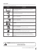
Safety Symbols This page depicts and describes safety symbols that may appear on this product. Read, understand, and follow all instructions on the machine before attempting to assemble and operate. Symbol Description READ THE OPERATOR’S MANUAL(S) Read, understand, and follow all instructions in the manual(s) before attempting to assemble and operate WARNING — ROTATING BLADES Do not put hands or feet near rotating parts or under the cutting deck. Contact with the blade(s) can amputate hands and feet.
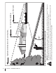
Section 2 — Safe Operation Practices d line (repr esent s a 15 ° slop e) Operate Z-Force-S zero turn tractors across the face of slopes rather than up and down. Begin with the first pass across the bottom of the slope and turn uphill at the end of each pass whenever possible. WARNING! Do not operate your lawn mower on such slopes. Do not mow on inclines with a slope in excess of 15 degrees (a rise of approximately 2-1/2 feet every 10 feet). A riding mower could overturn and cause serious injury.
3 Assembly & Set-Up Contents of Crate • One Lawn Tractor • One Oil Drain Hose • One Deck Wash Hose Coupler • One Z-Force S Tractor Operator’s Manual • One Engine Operator’s Manual • LPG Tank Strap Assemblies • One Hardware Pack Tractor Preparation Initial LPG Tank Fill-Up Unpacking the Tractor 1. Remove the upper crating material from the shipping pallet, and cut any bands or tie straps securing the tractor to the pallet. 2.
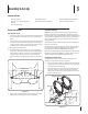
Installing the LPG Tank Steering Wheel Column 1. The steering wheel column is tilted all the way back for shipping purposes. To tilt the column forward, press the steering tilt pedal. Release the steering tilt pedal when the column is in the desired position. Open the straps and carefully place the LPG tank into the straps with the cylinder valve guard towards the left. Be sure that the alignment pin fits into the slot on the bottom of the cylinder valve guard. See Fig. 3-3.
Install Operator’s Seat Connecting the Battery Cables California Proposition 65 Warning! Battery posts, terminals, and related accessories contain lead and lead compounds, chemicals known to the State of California to cause cancer and reproductive harm. Wash hands after handling. To install the seat proceed as follows: NOTE: The seat is shipped with the seat switch and seat pan attached. A second person may be needed to hold the seat. 1. Cut any straps securing the seat assembly to the tractor.
4 Controls & Features LPG Tank Relief Valve Valve R TA H O 1/4 I1/2 ZON V OK F L E Ignition Switch Parking Break Module Engagement Lever L E R TICA A DD L.P.
PTO (Power Take-Off ) Switch Hour Meter/Indicator Panel The PTO switch is located on the LH console to the left of the operator’s seat. The hour meter/indicator panel is located on the LH console to the left of the operator’s seat. The PTO switch operates the electric PTO clutch mounted on the bottom of the engine crankshaft. Pull the switch knob upward to engage the PTO clutch, or push the knob downward to disengage the clutch.
Indicator Panel Features Drive Pedal Battery Indicator The drive pedal is located on the right side of the tractor, along the running board. Press the drive pedal forward to cause the tractor to travel forward. Ground speed is also controlled with the drive pedal. The further forward the pedal is pivoted, the faster the tractor will travel. The pedal will return to its original position when it’s not pressed.
5 Operation General Safety Before Operating Your Tractor • RECEIVE INSTRUCTION — Entirely read this operator’s manual. Learn to operate this machine SAFELY. Do not risk INJURY or DEATH. Allow only those who have become competent in its usage to operate this tractor. • Before you operate the tractor, study this manual carefully to familiarize yourself with the operation of all the instruments and controls. It has been prepared to help you operate and maintain your tractor efficiently.
Starting the Engine Cold Weather Starting Warning! This tractor is equipped with a safety interlock system designed for the protection of the operator. Do not operate the tractor if any part of the interlock system is malfunctioning. Periodically check the functions of the interlock system for proper operation. When starting the engine at temperatures near or below freezing, ensure the correct viscosity motor oil is used in the engine and the battery is fully charged. Start the engine as follows: 1.
Driving The Tractor Reverse Caution Mode WARNING! Avoid sudden starts, excessive speed and sudden stops. The REVERSE CAUTION MODE position of the key switch module allows the tractor to be operated in reverse with the blades (PTO) engaged. NOTE: Mowing in reverse is not recommended. 1. Release the parking brake. Move the throttle lever into the FAST (rabbit) position. 2. To travel FORWARD, slowly press the drive pedal forward until the desired speed is achieved. See Fig. 5-2.
Driving On Slopes • For best results it is recommended that the first two laps be cut with the discharge thrown towards the center. After the first two laps, reverse the direction to throw the discharge to the outside for the balance of cutting. This will give a better appearance to the lawn. • Do NOT attempt to mow heavy brush and weeds or extremely tall grass. Your tractor is designed to mow lawns, NOT clear brush. Keep the blades sharp and replace the blades when worn.
6 Maintenance & Adjustments Maintenance Schedule Check engine oil/LPG level Check Air Filter for Dirty, Loose or Damaged Parts Check LPG valve, hoses and seals Check hydraulic hoses for leaks Check tires & tire pressure Check deck, mower and hydro drive belts Check blades and blade bolt tightness Check safety switches for proper operation Check fluid level in transaxle expansion reservoir Before Each use Every 10 Hours P P P P P P P P P P P Every 25 Hours Every 50 Hours Every 100 Hours Clean mower
Maintenance Warning! Before performing any maintenance or repairs, disengage PTO, set parking brake, stop engine and remove key to prevent unintended starting. 5. Turn the oil drain valve 1⁄4-turn, then pull outward to begin draining oil. After the oil has finished draining, push the end of the oil drain valve back in and turn 1⁄4-turn to secure it back in place. Re-cap the end of the oil drain valve to keep debris from entering the drain port. 6.
7. 8. If exchanging tanks, be sure to use cylinders that contain LPG classified as HD-5 by National Gas Processors Association (NGPA) and cylinders that are designed & patented specifically for lawn care use as a vapor-delivery system. 2. Turn the reservoir cap counterclockwise to re-move, then check the oil level in the reservoir. Oil should be visible at the bottom of the cup, but the oil level must NOT be above the “FULL COLD” line. See Fig. 6-3. DO NOT FILL THE RESERVOIR.
Tractor Storage Cleaning the Tractor If your tractor is not going to be operated for an extended period of time (thirty days to approximately six months), the tractor should be prepared for storage. Store the tractor in a dry and protected location. If stored outside, cover the tractor (including the tires) to protect it from the elements. The procedures outlined below should be performed whenever the tractor is placed in storage. Any oil spilled on the machine should be wiped off promptly.
6. Move the tractor’s PTO (Blade Engage) into the ON position. Deck Spindle 7. Remain in the operator’s position with the cutting deck engaged for a minimum of two minutes, allowing the underside of the cutting deck to thoroughly rinse. 8. Move the tractor’s PTO (Blade Engage) into the OFF position. Grease fittings can be found on each deck spindle. See Fig. 6-6. Lubricate with 251H EP grease or an equivalent No. 2 multipurpose lithium grease.
2. Rotate the blade nearest the discharge chute so that it is parallel with the tractor. 3. Measure the distance from the front of the blade tip to the ground and the rear of the blade tip to the ground. The first measurement taken should be between 1⁄4” and 3⁄8” less than the second measurement. 4. Determine the approximate distance necessary for proper adjustment and proceed, if necessary. If the cutting deck appears to be mowing unevenly, a side to side adjustment can be performed.
Setting the Deck Wheels Adjusting the Seat Move the tractor on a firm and level surface, preferably pavement, and proceed as follows To adjust the position of the seat, push the seat adjustment lever to the left. Slide the seat forward or rearward to the desired position; then release the adjustment lever. Make sure seat is locked into position before operating the tractor. See Fig. 6-10. 1.
7 Service Warning! Before performing any service, place the PTO switch in the “OFF” position, engage the parking brake lever, turn the ignition key to the “OFF” position and remove the key from the switch. Charging the Battery Test and, if necessary, recharge the battery after the tractor has been stored for a period of time. • Battery Removal Warning! Battery posts, terminals and related accessories contain lead and lead compounds. Wash hands after handling. A voltmeter or load tester should read 12.
Deck Removal 5. Remove the mower deck from the tractor as follows: 1. Move the tractor to a level surface, disengage the PTO, stop the engine, and set the parking brake. 2. Place the deck lift pedal in the lowest mowing position and replace the lock pin in front of pedal in the deck height bracket and secure by locking the lock pin. See Fig. 7-3. Pull the cotter pins out of the four deck lift adjustment brackets. See Fig. 7-5. Cotter Pin Lock Pin Figure 7-5 Lowest Mowing Position Figure 7-3 3.
Deck Installation Install the deck on the tractor as follows: 1. Place the deck lift pedal in the highest mowing position and secure it by placing the click pin behind the pedal. Refer to Fig. 7-3. 2. Slide the deck under the tractor on the right side of the tractor lining up the deck lift adjustment brackets and the deck lift brackets on the deck. See Fig. 7-6. 5. After all four cotter pins are secure, slide the deck forward and hook the deck to the U-rod. 6. Route the belt as shown in Fig. 7-8.
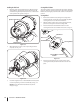
Replacing the Deck Belt 1. Remove the deck from beneath the tractor, (refer to Deck Removal on page 27). 2. Remove the hex washer screws securing the belt covers to the deck. 3. Using a 1⁄2” socket breaker bar or socket ratchet insert the male end into the 1⁄2” square opening in the lower idler arm assembly and pull the idler arm clockwise. See Fig. 7-9. While holding the idler arm back, loosen the deck belt from the pulley and slide the belt away from the pulley. 1.
Changing the Spindle Assembly 1. Remove the deck from beneath the tractor, (refer to Deck Removal on page 27). 2. Remove the hex washer screws securing the belt covers to the deck and remove the belt from the spindle pulleys. Refer to Fig. 7-9. 1. Remove the drive belts. (See Replacing the Belt) 2. Remove the blade. (See Mower Blade Care). 3. Use a 3⁄4” wrench to hold the hex nut on top of the spindle assembly when loosening the hex nut securing the blade.
8 Troubleshooting Problem Engine fails to start Cause Remedy 1. PTO/Blade Engage knob engaged. 1. Place knob in disengaged (OFF) position. 2. Parking brake not engaged. 2. Engage parking brake. 3. Spark plug wire(s) disconnected. 3. Connect wire(s) to spark plug(s). 4. Throttle control lever not in correct starting position. 4. Place throttle lever in the fast position. 5. LPG tank empty, or stale fuel. 5. Replace LPG tank. 6. Blocked fuel line. 6. Clear the blockage. 7.
9 Replacement Parts Component Part Number and Description 759-3336 Spark Plug KM-11013-7047 Air Filter Element KM-49065-7006 Oil Filter 32 01005376 Deck Belt 954-04262 PTO Belt 754-04250 Drive Belt 02005019 Mowing Blade 618-04426 Deck Spindle 734-04155 Deck Wheel 725-1750A Battery
Component Part Number and Description 746-04581 Throttle Control Cable 725-2054A Ignition Key 01006693 Chute Deflector 634-04128 Wheel Assembly 634-04629 Caster Wheel Assembly Section 9 — Replacement Parts 33
10 Attachments & Accessories 34 Part No. Part 19A70012100 60” Triple Bagger 19A70018100 Headlight Kit 19A70016100 Mulch Kit 59A30032150 33 lb.
Notes 11 35
Section 11— Notes
Section 11 — Notes 37
FEDERAL and/or CALIFORNIA EMISSION CONTROL WARRANTY STATEMENT YOUR WARRANTY RIGHTS AND OBLIGATIONS MTD Consumer Group Inc, the United States Environmental Protection Agency (EPA), and, for those products certified for sale in the state of California, the California Air Resources Board (CARB) are pleased to explain the emission (evaporative and/or exhaust) control system (ECS) warranty on your outdoor 2006 and later small off-road spark-ignited engine and equipment (outdoor equipment engine) In California, n
WARRANTED PARTS: The repair or replacement of any warranted part otherwise eligible for warranty coverage may be excluded from such warranty coverage if MTD Consumer Group Inc demonstrates that the outdoor equipment engine has been abused, neglected, or improperly maintained, and that such abuse, neglect, or improper maintenance was the direct cause of the need for repair or replacement of the part.
CUB CADET LLC MANUFACTURER’S LIMITED WARRANTY FOR Z-Force s/Z-Force ZERO-TURN RIDING MOWER IMPORTANT: To obtain warranty coverage owner must present an original proof of purchase and applicable maintenance records to the servicing dealer. Please see the operator’s manual for information on required maintenance and service intervals.