CubCadel\fr OPERATOR’S MANUAL CHIPPER SHREDDER- VACUUM Model CSv240 IMPORTANT: READ SAFETY RULES AND INSTRUCTIONS CAREFULLY Warning: This units equipped with an internal combustion engine and should not be used on or near any unimproved forest covered, brush-covered or grass-covered fans unless the engine’s exhaust system Is equipped with a spark arrested meeting applicable local of state laws {if any). if a spark arrested is used, it should be maintained in effective working order by the operator.
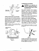
SECTION 1: FINDING YOUR MODEL NUMBER This Operator's Manual is an important part of your new chipper-shredder-vacuum. It will hap you assemble, prepare and maintain your unit. Please read and understand what it says. Before you start to prepare your chipper-shredder-vacuum for its first use, please locate the model plate and copy the information from it in this Operator's Manual. The information on the model plate is very important if you need help from your dealer or the customer support department.
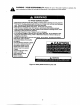
SECTION 3: IMPORTANT SAFE OPERATION PRACTICES A A A WARNING: THIS SYMBOL POINTS OUT IMPORTANT SAFETY INSTRUCTIONS WHICH, IF NOT FOLLOWED, COULD ENDANGER THE PERSONAL SAFETY AND/OR PROPERTY OF YOURSELF AND OTHERS. READ AND FOLLOW ALL INSTRUCTIONS IN THIS MANUAL BEFORE ATTEMPTING TO OPERATE YOUR CHIPPER-VACUUM. FAILURE TO COMPLY WITH THESE INSTRUCTIONS MAY RESULT IN PERSONAL INJURY. WHEN YOU SEE THIS SYMBOL-HEED ITS WARNING.
« Never operate unit without dither the inlet nozzle or optional hose attachment properly affixed to unit ‘These devices shield the operator from accidental contact with the rotating impeller. Never attempt to convert the unit from nozzle to hose mode or vice versa with the engine running. » Never attempt io remove or employ vacuum bag when engine is running. Shut the engine off and wait for the impeller fo come to a compete stop before removing the bag.
read, understand and follow the wakings and instructions in this manual and on the machine. n WARNING YOUR RESPONSIBILITY: Restrict the uss of this power machine to persons who TO AVOID SERIOUS INJURY + Read Owner's Manual and all safety labels on machine before starling and using machine, * Keep hands, feet, face, long hair and clothing out of chipper inlet, vac inlet, and discharge area. There are NOTATING BLADES inside these openings. * Wear approved safety glasses and gloves.
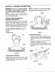
SECTION 4: ASSEMBLY INSTRUCTIONS IMPORTANT: This unit is shipped WITHOUT GASOLINE or OlL in the engine. After assembly, see separate engine operator’s manual for proper fuel and engine off recommendations. NOTE: To determine right and left hand sides of your chipper-shredder-vacuum, stand behind the unit, in the operating position. REMOVE CHIPPER-SHREDDER VACUUM FROM CARTON Remove staples, break glue on top flaps, or cut tape at carton end and peel along top flap to open carton.
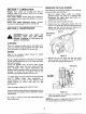
BEFORE USING YOUR CHIPPER-SHREDDER-VACUUM, REFER TO SECTION 3: IMPORTANT SAFE OPERATION PRACTICES OF THIS MANUAL. ALWAYS BE CAREFUL. e L) Ry standard glasses. The operation of any chipper-shredder-vacuum can result in foreign objects being thrown | into the eyes, which can damage your eyes severely. Always wear the safety glasses provided with this unit or eye shields before chipping, or while performing any adjustments or repairs.
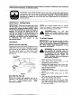
NOTE: You may hear a noise when reaching the start of the compression cycle. This noise is caused by the flails and fingers, which are part of the shredding mechanism, falling into place, and should be expected. In addition, the flails and fingers will be noisy after the engine is started, until the impeller reaches full speed. 7. Pull rope with a rapid, continuous, full am stroke. Keep a firm grip on starter handle. Let rope rewind slowly. Do not let starter handle snap back against starter. 8.
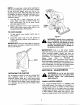
Smaller Hole / (Swivel Freely) ~ Larger Hole {Locked) Figure 9 NOZZLE DOOR HEIGHT ADJUSTMENT The nozzle door can be adjusted to any of five positions, ranging from 1/2" to 3" ground clearance. See Figure 10. The nozzle door height has to be adjusted according to the conditions. Slide the height adjustment lever forward or backward for adjusting the nozzle door upwards or downwards. Height must be adjusted equally.
SECTION 7: LUBRICATION Wheels Rear wheels are provided with light oil pairings. Place a few drops of SAE 30 oil on each bearing once a season. Front caster wheels Grease tiffing are provided for easy lubrication of the swivel pins located on the front caster wheel. Nozzle door height adjustment levers Lubricate nozzle door height adjustment levers with fight oil. SECTION 8: MAINTENANCE disconnect spark plug wire before cleaning, lubricating or performing any repairs or maintenance.
5 SHARPENING OR REPLACING CHIPPER BLADES 1. Disconnect the spark plug wire and ground it away from the spark plug. 2. Remove the flail screen as instructed in the previous section, 3. Remove the plastic bat cover on the front of the engine by removing the two deli-tapping screws. See Figure 14, Belt N Cover Self-Tapping Screws Figure 14 4. Open access plate by removing the two hex dock nuts. See Figure 15.
8. Tip the unit backwards so that it rest on the handles. 8. Remove the lower belt guard by removing the two self-tapping screws, See Figure 17, | Se-Tapping 2 “, S. Borews Selim-Tapping Screws Figure 17 10, Remove the safety switch from the front of the outer housing by removing the two self-tapping screws. See Figure 17, 11. Remove the two hex bolts and hex lock nuts which extend through the housing. Lift the flail screen out of the housing. See Figure 13. 12.
19, Press down on the belt guard spring by the idler pulley and release spring from the soot on the idler bracket. Place the belt on the idler pulley and place belt guard spring back into the slot on the idler bracket. See Figure 20. Place the mounting adapter against the engine. Make sure the hole in the mounting adapter is facing up. See Figure 20. Place the inner housing against mounting adapter and frame. Secure with the five hex bolts and two hex nuts removed in step 17.
SECTION 11; TROUBLE SHOOTING GUIDE Trouble Possible Cause(s) Corrective Action Engine fails to start Dirty air cleaner, Fue! tank empty or stale fuel. Spark plug wire disconnected. Cannot pull recoil cord. Choke not in ON position. Faulty spark plug. Nozzle safety switch not depressed. Hester (G the engineering manual packed with your unit. Fill tank with clean, fresh gasoline. Fuse will rot last over thirty days unless a fuel stabilizer is added. Connect wire to spark plug. Obstruction lodged in impeller.
Model CSV240 REF. FART DESCRIPTION NO. NO. i 1661-0095 Chipper Chi its 2 |712:8010 Hex Nut 3 1786-0242 Bell Washer .340 1D x 872 OD 4 |731-1838A Discharge Chute 5 1764-0492 Bag 8 6310070 Nozzle Asm 7 |731-1831 Nozzle Flap 8 |710-0869 Sower 9 1720-0190 Height Adjustment Knob 10 |732-0754 Spring Lever 11 1781-0702 Index Bracket RH 12 |781-0703 index Bracket LH 13 [712.
Model CSV240 REF PART DESCRIPTION REF. PART DESCRIPTION 1681-0776 Impeller Ass’y Complete 18 |681-0008 Housing Says inner Fail 2 |718-0329 Flail Blade 18 17810599 Upper Shredder Blade 3 |715-0166 Spiro Pin 21 [7360119 Lock Wagner 5/16 4 |881-0107 Impeller Assembly 22 7100772 Hex Cap Screw x 2 5 711-08338 Clevis Pin 23 |781-0653 Flail Housing Blade 8 |736-0118 Lack Washer 5/16 24 1710-3008 Hex Gap Screw x .75 7 7101054 Cap Screw x 1.
Model CSV240 IMPORTANT: For a proper working machine, USA Factory Approved Parts, v-Belts are specially designed to engage and disengage safely. A substitute (non OEM) V-belt can | be dangerous by not disengaging completely. I REF. PART DESCRIPTION REF. PRAY DESCRIPTION |781-0677 Chain Case LH 634-0129 Rim Asm Complete 2 |781-0876 Chain Ass RH 734-0210 Pneumatic Tire 10.0x 4.0 3 |754-0457 V-Belt 734-0255 Valve 4 7480313 Spacer 741-0487A Flange Bearing .632 D 5 |741-0413 Hex Flange Bearing 14 |712.
Model CSV240 REF. PART DESCRIPTION REF. PART DESCRIPTION [618-0255 Transmission Assembly Complete 18 |736-0520 Flat Washer 504 |[18500A Hex Bearing Cup 20 |741-0479 Thrust Bearing .375 (D x .812 OD 3 {711-1118 Output Shaft 6T Sprocket 21 {656-0008 Pulley Ass’y Idler wi Bearing 4 1717-1432 Helical 34T Gear 22 17410556 Needier Bearing .375 D x .875 OD 5 [721-0213 Oil Seal 23 [710-0589 Hex Si crew #10-16 x .75 6 |736-0187 Flat Washer .
Model CSV240 REF. PART DESCRIPTION REF. PART DESCRIPTION [748-0996 Upper Handle 25 1710-0187 Hex Cap Screw % .75 2 {1539-019 Push Nut 26 |710-3103 Hex Cap Screw x 1,75 3 7110737 Stud Pin .250 x 1.75 27 [748-0980 Lower Push Han die 4 1746-0714 Clutch Cable 56* 28 1710-0502A Sower x 1.25 5 7311735 Upper Clutch Cover 29 [710-0604 Hex Washer Screw x 625 6 |731-0620 Drive Lever 30 |741-0413 Hex Flange Bearing .631 x.720 7 7311738 Lower Clutch Cover 31 1681-0097A Frame Asm 8 \710-0841 Brew #10-12 % .
MANUFACTURER’S LIMITED WARRANTY FOR: Subclass \y TWO-YEAR RESIDENTIAL ONE-YEAR COMMERCIAL Proper maintenance of your Cub Cadet equipment is the owner’s responsibility. Follow the instructions in your operator's manual for correct lubricants and maintenance schedule.