Safe Operation Practices • Set-Up • Operation • Maintenance • Service • Troubleshooting • Warranty Operator’s Manual Yard Vacuum/Chipper/Shredder with Vacuum/Hose Model CSV 050 WARNING READ AND FOLLOW ALL SAFETY RULES AND INSTRUCTIONS IN THIS MANUAL BEFORE ATTEMPTING TO OPERATE THIS MACHINE. FAILURE TO COMPLY WITH THESE INSTRUCTIONS MAY RESULT IN PERSONAL INJURY. CUB CADET LLC, P.O. BOX 361131 CLEVELAND, OHIO 44136-0019 Printed In USA Form No.
1 To The Owner Thank You Thank you for purchasing a Chipper/Shredder Vacuum manufactured by Cub Cadet LLC. It was carefully engineered to provide excellent performance when properly operated and maintained. Please read this entire manual prior to operating the equipment. It instructs you how to safely and easily set up, operate and maintain your machine. Please be sure that you, and any other persons who will operate the machine, carefully follow the recommended safety practices at all times.
Important Safe Operation Practices 2 WARNING: This symbol points out important safety instructions which, if not followed, could endanger the personal safety and/or property of yourself and others. Read and follow all instructions in this manual before attempting to operate this machine. Failure to comply with these instructions may result in personal injury.
Safe Handling of Gasoline: 4. To avoid personal injury or property damage use extreme care in handling gasoline. Gasoline is extremely flammable and the vapors are explosive. Serious personal injury can occur when gasoline is spilled on yourself or your clothes which can ignite. Wash your skin and change clothes immediately. 1. Use only an approved gasoline container. 2. Never fill containers inside a vehicle or on a truck or trailer bed with a plastic liner.
Maintenance & Storage Do not modify engine 1. Never tamper with safety devices. Check their proper operation regularly. 2. Check bolts and screws for proper tightness at frequent intervals to keep the machine in safe working condition. Also, visually inspect machine for any damage and repair, if needed. To avoid serious injury or death, do not modify engine in any way. Tampering with the governor setting can lead to a runaway engine and cause it to operate at unsafe speeds.
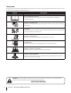
Safety Symbols This page depicts and describes safety symbols that may appear on this product. Read, understand, and follow all instructions on the machine before attempting to assemble and operate. Symbol Description READ THE OPERATOR’S MANUAL(S) Read, understand, and follow all instructions in the manual(s) before attempting to assemble and operate WARNING— ROTATING BLADES Keep hands out of inlet and discharge openings while machine is running.
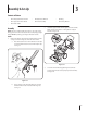
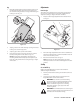
3 Assembly & Set-Up Contents of Carton • One Chipper/Shredder Vacuum • One Operator’s Manual • One Bag • One Upper and Lower Handle • One Hose Assembly • One Safety Glasses • One Bottle of Oil Assembly 2. NOTE: This unit is shipped without gasoline or oil in the engine. Fill up gasoline and oil as instructed in the accompanying engine manual BEFORE operating your chipper shredder vacuum. Unfold the upper handle until it aligns with lower handle.
4. Loosen the wing nut that secures the rope guide to the right side of upper handle. a. Slowly pull starter rope out of engine. b. Slip the starter rope into the rope guide. Tighten the wing nut. See Fig. 3-3. 2. Pull spring loaded pin out on the base and align pin with the first hole (closest to the end of the tube) in the hose adapter. See Fig. 3-4B. 3. Release the pin to lock the hose in place. 4. Lay hose tubing in curved end of hose handle next to chipper chute and into hose cradle. See Fig.
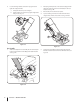
Adjustments Bag 1. Grasp bag handle with one hand and slide locking rod on mounting bracket with other hand toward engine. Use the end of mounting bracket as leverage when sliding the locking rod. See Fig. 3-6. Nozzle Height The nozzle can be adjusted to any six positions, ranging from 5/8” to 4 1/8” ground clearance. The nozzle height has to be adjusted according to chipper shredder conditions. 1. 3 Depress nozzle height adjustment lever towards wheel. See Fig. 3-7. 2 2 1 4 3 1 Figure 3-6 2.
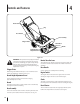
4 Controls and Features Recoil Starter Bag Hose Handle Hose Assembly Chipper Chute Nozzle/Hose Vac Lever Nozzle Nozzle Height Adjustment Lever Figure 4-1 WARNING: The operation of any chipper shredder can result in foreign objects being thrown into the eyes, which can damage your eyes severely. Always wear the safety glasses provided with this unit or eye shields while operating or while performing any adjustments or repairs.
5 Operation Starting Engine Stopping Engine 1. 1. Turn off the engine switch. 2. Disconnect spark plug wire and ground against the engine to prevent unintended starting. Pull out the choke knob located on the engine. See Fig. 5-1 inset. NOTE: Use of the choke may not be necessary if the engine is warm or the air temperature is high. To Empty Bag 1. Unhook bag straps from the lower handle. 2. Unsnap bag clip from the top of lower handle. See Fig. 5-2.
Buttons Inner Flap Outer Flap Figure 5-3 8. Twist the buttons to lock bag. Place bag back onto unit as instructed in Assembly & Set-Up. WARNING: Do not at any time make any Figure 5-4 Using The Hose Assembly 1. adjustments without first stopping engine and disconnecting spark plug wire. Place nozzle/hose vac lever in the bottom position on the nozzle to redirect vacuum to the hose assembly. See Fig. 5-5A.
6 Maintenance & Adjustments Maintenance Equipment Care General Recommendations • Clean the chipper/shredder vacuum thoroughly after each use. • Always observe safety rules when performing any maintenance. • Wash bag periodically with water. Allow to dry thoroughly in shade. • The warranty on this chipper/shredder vacuum does not cover items that have been subjected to operator abuse or negligence. To receive full value from warranty, operator must maintain the equipment as instructed here.
WARNING: Before performing any type of maintenance on the machine, wait for all parts to stop moving and disconnect the spark plug wire. Failure to follow this instruction could result in personal injury or property damage. 6. Remove and clean the screen by scraping or washing with water. See Fig. 6-3. Removing the Flail Screen If the discharge area becomes clogged, remove the flail screen and clean area as follows: 1. Stop the engine.
7 Service Blade Care Front Support Brace/ Lock Nut WARNING: Before performing any type of maintenance on the machine, wait for all parts to stop moving and disconnect the spark plug wire. Failure to follow this instruction could result in personal injury or property damage. Bell Washer Thrust Washer NOTE: When tipping the unit, empty the oil and fuel tank and keep engine spark plug side up. 1. Disconnect and ground the spark plug wire to retaining post. 2. Remove bag assembly or blower chute. 3.
7. Carefully tilt and support the unit up to provide access underneath to the nozzle mounting hardware and impeller. Remove the three shoulder bolts securing the black plastic lower flail housing to the lower housing. Refer to Fig. 7-4. 10. The nuts on the flat head cap screws can be reached from underneath using a 1/2-inch socket, universal, and extension. See Fig. 7-6. Impeller Nuts Figure 7-6 Figure 7-4 8. Tilt top of black plastic lower flail housing toward the engine to remove. 9.
8 Troubleshooting Problem Engine Fails to start Cause Remedy 1. Throttle lever (if equipped) not in correct starting position. 1. Move throttle lever to FAST or START position. 2. Engine switch (if equipped) in OFF position. 2. Move engine switch to ON position. 3. Spark plug wire disconnected. 3. Connect wire to spark plug. 4. Choke not in CHOKE position (if equipped). 4. Move choke lever to CHOKE position. 5. Fuel tank empty or stale fuel. 5. Fill tank with clean, fresh gasoline. 6.
9 Engine Operation Fuel Cap Air Cleaner Starter Grip Oil Fill Cap Spark Plug Figure 9-1 Pre-Operation Check 10w Oil Recommendations 20w NOTE: This engine is shipped without gasoline or oil in the engine. Running the engine with insufficient oil can cause serious engine damage and void the engine warranty. • 1 Before starting engine, fill with oil. Do not over-fill. Oil capacity is about 20 oz.
Check Oil Level Check Fuel Level NOTE: Be sure to check the engine on a level surface with the engine stopped. 1. Clean around fuel fill before removing cap to fuel. 2. Fill tank to approximately 1-inch below lowest portion of neck to allow for fuel expansion. Be careful not to overfill. 1. Remove the oil filler cap and wipe the dipstick clean. See Fig. 9-2. NOTE: Before refueling, allow engine to cool 2 minutes.
10 Engine Maintenance WARNING: Shut off the engine before performing any maintenance. To prevent accidental start-up, disconnect the spark plug boot. IMPORTANT: If engine must be tipped to transport equipment or to inspect or remove grass, keep spark plug side of engine up. Transporting or tipping engine spark plug down may cause smoking, hard starting, spark plug fouling, or oil saturation of air cleaner.
Oil Service Air Cleaner Service • Check oil level regularly. • Be sure correct oil level is maintained. Check every five hours or daily before starting engine. See oil checking procedure in the Operation section. Paper filters cannot be cleaned and must be replaced once a year or every 100 operating hours; more often if used in extremely dusty conditions. WARNING: Never use gasoline or low flash point solvents for cleaning the air cleaner element. A fire or explosion could result.
Spark Plug Service 3. WARNING: DO NOT check for spark with spark plug removed. DO NOT crank engine with spark plug removed. Measure the plug gap with a feeler gauge. Correct as necessary by bending side electrode. See Fig. 10-4. The gap should be set to 0.030 in. To ensure proper engine operation, the spark plug must be properly gapped and free of deposits. 1. Remove the spark plug boot and use a spark plug wrench to remove the plug. See Fig. 10-3. Electrode Spark Plug 0.030 in. Figure 10-4 4.
Fuel Filter Service Storage The fuel filter cannot be cleaned and must be replaced once a year or every 100 operating hours; more often if run with old gasoline. Engines stored between 30 and 90 days need to be treated with a gasoline stabilizer and engines stored over 90 days need to be drained of fuel to prevent deterioration and gum from forming in fuel system or on essential carburetor parts.
Model CSV 050 2 54 8 6 53 5 34 9 3 11 34 7 22 10 12 17 36 50 18 4 20 14 16 13 15 20 56 27 57 24 20 38 7 55 40 37 21 44 41 25 26 51 43 52 28 48 29 30 50 50 46 33 39 1 47 35 42 45 49 31 28 32 24 23 19
Model CSV 050 Ref No. Part Number Ref No. Part Number 1 936-0314 Thrust Washer.375 ID x.70 OD 30 764-0648A Vacuum Hose 2 3 749-04172-0637 Upper Handle 31 720-0369 Handle Plug 720-0279 Knob 32 731-06469 Hose Adapter 4 710-0599 Screw, 1/4-20 x.500 33 912-0442 Cap Lock Nut, 1/4-20 5 710-1205 Eye Bolt 34 710-1611B TT Screw, 5/16-18 x .750 6 781-1056-0637 Upper Handle Bracket 35 781-04082-0637 Front Wheel Support Brace 7 710-0726 Hex Cap Screw 5/16-12 x.
Model CSV 050 34 35 37 36 38 30 1 39 40 42 41 44 48 43 44 30 46 28 44 29 B 47 49 45 11 4 2 3 15 11 10 9 31 33 8 7 16 B 13 5 32 19 6 A 22 23 17 A 24 14 12 25 26 21 20 27 26 18
Model CSV 050 Ref No. 1 Part Number Description 664-04040 Bag Assembly Ref No. 26 Part Number 732-1151A Description Nozzle Door Torsion Spring 2 681-0154-0637 Screen Assembly 27 731-2294A Nozzle Door 3 710-1054 Hex Screw 5/16-24 x 1.0 28 664-04040 Bag 4 981-0490 Chipper Blade 29 631-0083 Chute Assembly 5 781-0735 Pin Clip 30 710-0726 Hex Index Screw, 5/16-12 x.750 6 719-0329 Flail 31 736-0247 Flat Washer.375 ID x 1.
Engine Model - 1P70C0 21 29 15 8 9 29 20 30 1 7 3 2 19 13 18 24 17 25 31 26 28 10 11 6 5 4 12 14 27 32 23 16 28 22
Engine Model - 1P70C0 Ref No. Part Number 1. 951-10368 Fuel Tank 2. 951-10369 Flywheel Shroud 3. 951-10335 Rubber Fuel Tank Mounting Washer 4. 951-10334 Oil Filler Tube Assembly 5. 951-10852 Dipstick Assembly 6. 951-10413 Cylinder Head Complete 7. 951-10932 Short Block Assembly 8. 951-10936 On/Off Switch and Bracket Assembly 9. 951-10319 Recoil Spring and Pulley Assembly 10. 751-10344 Push Rod Kit 11. 951-10345 Valve Kit 12.
Cub Cadet LLC (Cub Cadet), the California Air Resources Board (CARB) and the United States Environment Protection Agency (U. S. EPA) Emission Control System Warranty Statement (Owner’s Defect Warranty Rights and Obligations) EMISSION CONTROL SYSTEM COVERAGE IS APPLICABLE TO CERTIFIED ENGINES PURCHASED IN CALIFORNIA IN 2005 AND THEREAFTER, WHICH ARE USED IN CALIFORNIA, AND TO CERTIFIED MODEL YEAR 2005 AND LATER ENGINES WHICH ARE PURCHASED AND USED ELSEWHERE IN THE UNITED STATES.
(4) Repair or replacement of any warranted part under the warranty provisions of this article must be performed at no charge to the owner at a warranty station. (5) Notwithstanding the provisions of Subsection (4) above, warranty services or repairs must be provided at all Cub Cadet LLC distribution centers that are franchised to service the subject engines.
CUB CADET LLC MANUFACTURER’S LIMITED WARRANTY FOR Chipper-shredders & Chipper-shredder VACUUMs The limited warranty set forth below is given by Cub Cadet LLC with respect to new merchandise purchased and used in the United States, its possessions and territories, and by MTD Products Limited with respect to new merchandise purchased and used in Canada and/or its territories and possessions. c.