
Warranty

3
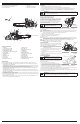
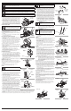
KNOW YOUR UNIT
2
1
18
1
0
16
A
PPLICATIONS
T
his unit may be used for the purposes listed below:
•
Basic limbing, felling and woodcutting
•
Removing buttress roots
3
14
8
1
13
1
7
6
7
G
uide Bar Tip
24
5
9
1
2
20
1
1
4
15
2
3
1
. GUIDE BAR
2
. LOW KICKBACK SAW CHAIN
3
. CHAIN-TENSIONING SCREW
4
. SPARK ARRESTER SCREEN
5
. CHAIN BRAKE LEVER /FRONT HAND GUARD
6
. FRONT HANDLE
7
. STARTER HANDLE
8. SPARK PLUG
9
. AIR FILTER COVER
10. STOP SWITCH
11. SAFETY LATCH
12. BAR LUBE RESERVOIR CAP
22
1
9
2
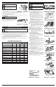
S
AFETY FEATURES
Numbers preceding the descriptions correspond with the numbers above to help you locate the safety feature.
2
. LOW KICKBACK SAW CHAIN helps significantly reduce kickback, or the intensity of kickback, due to specially
designed depth gauges and guard links.
4. SPARK ARRESTER SCREEN retains carbon and other flammable particles over 0.023 inches (0.6mm) in size from
engine exhaust flow. Compliance with local, state and federal laws and/or regulations governing the use of a spark
a
rrester screen is the user’s responsibility. See Safety Information for additional information.
5
. CHAIN BRAKE LEVER / FRONT HAND GUARD helps protects the operator’s left hand in the event it slips off the
f
ront handle while the unit is running.
C
HAIN BRAKE is designed to reduce the possibility of injury due to kickback by stopping a moving saw chain in
milliseconds. It is activated when pressure is applied to the chain brake lever, as in the event of the operator’s hand
striking the lever during kickback.
10. STOP SWITCH immediately stops the engine when moved to the STOP position. The stop switch must be pushed
t
o the RUN position to start or restart the engine.
11. SAFETY LATCH prevents accidental acceleration of the engine. The throttle control trigger (20) cannot be squeezed
u
nless the safety latch is depressed.
2
0. CHAIN CATCHER reduces the danger of injury in the event the saw chain breaks or derails during operation. The
chain catcher is designed to intercept a whipping chain.
1
3. STARTER COVER
1
4. FUEL TANK CAP
1
5. REAR HANDLE / BOOT LOOP
1
6. PRIMER BULB
1
7. CHOKE LEVER
1
8. BAR-RETAINING NUTS
19. THROTTLE CONTROL TRIGGER
20. CHAIN CATCHER
21. MUFFLER SHIELD
22. GUIDE BAR COVER
23. SPIKED BUMPER / BUCKING SPIKE
2
4. MULTI-PURPOSE TOOL
CHAIN SAW COMPONENTS
T
his unit requires assembly.
U
NPACKING
•
Carefully remove the product and any accessories from the box.
•
Inspect the product carefully to make sure no breakage or damage occurred during shipping.
•
Do not discard the packing material until you have carefully inspected and satisfactorily operated the product.
• If any parts are damaged or missing, please call
1-877-282-8684 (U.S.) or 1-800-668-1238 (Canada)
for
a
ssistance.
ASSEMBLING THE GUIDE BAR AND SAW CHAIN
Refer to Removing/Replacing the Guide Bar and Chain in the
Maintenance and Repair Instructions section.
ADDING BAR AND CHAIN LUBRICANT
The guide bar and saw chain require lubrication to minimize friction.
Never starve the guide bar and chain of lubricating oil. Running the
unit without enough oil will decrease cutting efficiency, shorten the
l
ife of the saw chain, cause rapid dulling of the saw chain and
e
xcessive wear to the guide bar from overheating. An insufficient
a
mount of lubricating oil is evidenced by smoke, guide bar
discoloration or pitch build-up.
F
ill the bar lube reservoir each time the fuel tank is filled. Only use bar and chain oil that is formulated to perform over a
w
ide range of temperatures with no diluting required in the bar lube reservoir. Do not use motor oil or any other
petroleum-based oil.
NOTE: This chain saw comes from the factory with the bar lube reservoir empty. Use the bottle of bar and chain oil that
i
s included with the unit.
NOTE: Always clean the bar lube reservoir cap and surrounding area before adding bar and chain lubricant. Use a
damp cloth. This helps prevent debris from entering the bar lube reservoir.
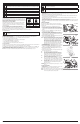
1. Remove the bar lube reservoir cap (Fig. 4).
2. Carefully pour the bar and chain oil into the bar lube reservoir.
3. Replace the bar lube reservoir cap and tighten securely.
4. Wipe off excess oil.
NOTE: Bar lube reservoirs are designed to keep oil slowly flowing onto the chain. This unit will use approximately one
t
ank of bar and chain oil for every tank of fuel. If the oil flow to the guide bar and chain is too much or too little,
r
efer to Adjusting the Automatic Oiler in the Maintenance and Repair Instructions section.
N
OTE: Do not use dirty, used or otherwise contaminated oils. Damage may occur to the guide bar or chain.
I
MPORTANT! Please dispose of oil properly. Consult your local waste
a
uthority for information regarding available disposal options.
F
UELING THE ENGINE
T
his unit is designed to operate on a mixture of unleaded gasoline
a
nd 2-cycle engine oil. Refer to Oil and Fuel Information for complete
mixing instructions and detailed fuel requirements.
NOTE: Always clean the fuel tank cap and surrounding area before
fueling the unit. Use a damp cloth. This helps prevent debris
f
rom entering the fuel tank.
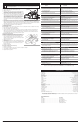
1
. Turn the unit on its side so that the fuel tank is facing up (Fig. 5).
2
. Slowly unscrew and remove the fuel tank cap by turning it
c
ounterclockwise.
3
. Slowly pour the proper fuel/oil mixture into the fuel tank until the
tank is full.
4
. Replace the fuel tank cap and turn it clockwise to secure it tightly.
5
. Wipe off any spilled fuel.
T
ESTING THE CHAIN BRAKE
Always test the chain brake before using the unit and periodically
d
uring operation. Follow these instructions to make sure the chain
b
rake is working correctly:
1
. Place the unit on a clear, firm and flat surface.
2
. Pull the chain brake lever back to disengage the chain brake.
3
. Start the unit. Refer to Starting and Stopping Instructions. Be sure
t
o maintain a proper grip. Refer to Proper Grip on Handles in the Operating Instructions section.
4
. While the unit is running, squeeze the throttle control trigger to 1/3 throttle and then engage the chain brake by
pushing the chain break lever forward with the left hand (Fig. 6).
The chain should stop moving abruptly. If it does, immediately release the throttle control trigger, turn off the engine and
return the chain brake to the disengaged position. Refer to Starting and Stopping Instructions.
If the chain does not stop when the chain brake is engaged, release the throttle control trigger, stop the engine and have
the unit serviced by an authorized service center.
ASSEMBLY INSTRUCTIONS
WARNING: Make sure the bar lube reservoir is
always filled. Failure to fill the bar lube reservoir will
cause irreparable damage to the unit.
Fig. 4
Bar Lube
Reservoir
B
ar Lube
Reservoir Cap
Fig. 5
Fuel Tank
C
ap
F
uel Tank
Fig. 6
Chain Brake
WARNING: Make sure the stop switch is in the STOP position before inspecting, adjusting, fueling or
performing maintenance on any part of the unit. Failure to do so can result in serious personal injury.
R
efer to Starting and Stopping Instructions.
WARNING: T
he chain must not move when the engine runs at idle speed. If it does move at idle
speed, refer to the Carburetor Adjustment instructions in the Maintenance and Repair Instructions
section. Avoid contact with the muffler. A hot muffler can cause serious burns.
WARNING: W
hen activating the chain brake, do
so slowly and deliberately. Keep the saw chain from
t
ouching anything; don’t let the saw tip forward.
T
OOLS REQUIRED:
•
Damp Cloth
•
Small Flathead Screwdriver
•
Multi-purpose Tool (included)