Safe Operation Practices • Set-Up • Operation • Maintenance • Service • Troubleshooting • Warranty Operator’s Manual Hydrostatic Lawn Tractor — LTX 1042 WARNING READ AND FOLLOW ALL SAFETY RULES AND INSTRUCTIONS IN THIS MANUAL BEFORE ATTEMPTING TO OPERATE THIS MACHINE. FAILURE TO COMPLY WITH THESE INSTRUCTIONS MAY RESULT IN PERSONAL INJURY. CUB CADET LLC, P.O. BOX 361131 CLEVELAND, OHIO 44136-0019 Printed In USA Form No.
1 To The Owner Thank You Thank you for purchasing a Lawn Tractor manufactured by Cub Cadet LLC. It was carefully engineered to provide excellent performance when properly operated and maintained. Please read this entire manual prior to operating the equipment. It instructs you how to safely and easily set up, operate and maintain your machine. Please be sure that you, and any other persons who will operate the machine, carefully follow the recommended safety practices at all times.
Important Safe Operation Practices 2 WARNING! This symbol points out important safety instructions which, if not followed, could endanger the personal safety and/or property of yourself and others. Read and follow all instructions in this manual before attempting to operate this machine. Failure to comply with these instructions may result in personal injury. When you see this symbol.
12. A missing or damaged discharge cover can cause blade contact or thrown object injuries. 13. Stop the blade(s) when crossing gravel drives, walks, or roads and while not cutting grass. 14. Watch for traffic when operating near or crossing roadways. This machine is not intended for use on any public roadway. Slopes are a major factor related to loss of control and tip-over accidents which can result in severe injury or death. All slopes require extra caution.
Service Children 1. Tragic accidents can occur if the operator is not alert to the presence of children. Children are often attracted to the machine and the mowing activity. They do not understand the dangers. Never assume that children will remain where you last saw them. a. Keep children out of the mowing area and in watchful care of a responsible adult other than the operator. b. Be alert and turn machine off if a child enters the area. c.
Periodically check to make sure the blades come to complete stop within approximately (5) five seconds after operating the blade disengagement control. If the blades do not stop within the this time frame, your machine should be serviced professionally by an authorized MTD Service Dealer. Do not modify engine 4. Check brake operation frequently as it is subjected to wear during normal operation. Adjust and service as required. Notice Regarding Emissions 5.
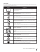
Safety Symbols This page depicts and describes safety symbols that may appear on this product. Read, understand, and follow all instructions on the machine before attempting to assemble and operate. Symbol Description READ THE OPERATOR’S MANUAL(S) Read, understand, and follow all instructions in the manual(s) before attempting to assemble and operate DANGER— ROTATING BLADES Never carry passengers. Never carry children, even with the blades off.
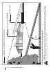
Section 2 — Important Safe Operation Practices d line (repr esent s a 15 ° slop e) WARNING! Do not operate your lawn mower on such slopes. Do not mow on inclines with a slope in excess of 15 degrees (a rise of approximately 2-1/2 feet every 10 feet). A riding mower could overturn and cause serious injury. Operate riding mowers up and down slopes, never across the face of slopes. Use this page as a guide to determine slopes where you may not operate safely.
3 Assembly & Set-Up Contents of Crate • One Lawn Tractor • • One Lawn Tractor Operator’s Manual • One Oil Drain Tube One Deck Wash Hose Coupler One Kohler Engine Operator’s Manual Tractor Set-Up Shipping Brace Removal Warning! Make sure the lawn tractor’s engine is off, set the parking brake and remove the ignition key before removing the shipping brace.
Attaching the Negative Battery Cable Setting the Deck Gauge Wheels NOTE: The positive battery terminal is marked Pos. (+). The negative battery terminal is marked Neg. (–). Move the tractor on a firm and level surface, preferably pavement, and proceed as follows The positive cable (heavy red wire) is secured to the positive battery terminal (+) with a hex bolt and hex nut at the factory. 1.
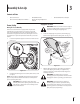
Adjusting the Seat To adjust the position of the seat, pull up and hold the seat adjustment lever. Slide the seat forward or rearward to the desired position; then release the adjustment lever. Make sure seat is locked into position before operating the tractor. See Fig. 3-5. Figure 3-5 Warning! Before operating the tractor, make sure the seat is engaged in the seat-stop. Engage the parking brake. Stand behind the machine and pull back on seat until it clicks into place.
4 Controls and Features Systems Indicator Monitor Fuel Tank Cap Ignition Switch Module Throttle/Choke Control Fuel Level Indicator Drive Pedal Brake Pedal Cargo Net Seat Adjustment Lever Parking Brake/ Cruise Control Lever Reverse Pedal Deck Lift Lever PTO (Blade Engage) Handle Storage Bin Cup Holder Figure 4-1 Lawn Tractor controls and features are illustrated in Fig. 4-1 and Brake Pedal described on the following pages.
Deck Lift Lever Systems Indicator Monitor / Hour Meter LCD Found on your tractor’s right fender, the deck lift lever is used to change the height of the cutting deck. To use, move the lever to the left, then place in the notch best suited for your application. Ignition Switch Module Warning! Never leave a running machine unattended. Always disengage PTO, set parking brake, stop engine and remove key to prevent unintended starting.
Fuel Level Indicator 100% The Fuel Level Indicator is located on the left side of the tractor’s dash and indicates the amount of fuel in the gas tank. 50% 0% PTO / Blade Engage Handle Activating the PTO engages power to the cutting deck or other (separately available) attachments. Push forward on the PTO/ Blade Engage handle to activate it. Pull the PTO/ Blade Engage handle back to disengage the power to the cutting deck or other (separately available) attachments.
5 Operation Starting the Engine TO AVOID SERIOUS INJURY OR DEATH • • • • • • • • • GO UP AND DOWN SLOPES, NOT ACROSS. AVOID SUDDEN TURNS. DO NOT OPERATE THE UNIT WHERE IT COULD SLIP OR TIP. IF MACHINE STOPS GOING UPHILL, STOP BLADE(S) AND BACK DOWNHILL SLOWLY. KEEP SAFETY DEVICES (GUARDS, SHIELDS, AND SWITCHES, ETC.) IN PLACE AND WORKING. REMOVE OBJECTS THAT COULD BE THROWN BY THE BLADE(S). KNOW LOCATION AND FUNCTION OF ALL CONTROLS.
Driving The Tractor Reverse Caution Mode WARNING! Avoid sudden starts, excessive speed and sudden stops. The REVERSE CAUTION MODE position of the key switch module allows the tractor to be operated in reverse with the blades (PTO) engaged. NOTE: Mowing in reverse is not recommended. 1. Lightly press the brake pedal to release the parking brake. Move the throttle lever into the FAST (rabbit) position. 2. To travel FORWARD, slowly press the drive pedal forward until the desired speed is achieved.
Driving On Slopes Cruise Control Warning! Never engage the cruise control lever while traveling in reverse. Refer to the SLOPE GAUGE on page 7 to help determine slopes where you may operate the tractor safely. WARNING! Do not mow on inclines with a slope in excess of 15 degrees (a rise of approximately 2-1⁄2 feet every 10 feet). The tractor could overturn and cause serious injury. To set the cruise control: 1.
Engaging the PTO Engaging the PTO transfers power to the cutting deck or other (separately available) attachments. To engage the PTO: 1. Move the Throttle/Choke control lever to the FAST (rabbit) position. 2. Push the PTO/Blade Engage lever forward into the engaged (ON) position. NOTE: Always operate the tractor with the Throttle/Choke control lever in the FAST (rabbit) position for the most efficient use of the cutting deck or other (separately available) attachments.
6 Maintenance & Adjustments Maintenance Schedule Before Each use Every 10 Hours Check Air Filter for Dirty, Loose or Damaged Parts Every 50 Hours Every 100 Hours P Clean Hood/Dash Louvers Check Engine Oil Level Every 25 Hours Prior to Storing P P P P Clean and Re-oil Air Filter’s Foam Precleaner P Replace Air Filter Element P Change Engine Oil and Replace Oil Filter Clean Battery Terminals P P P P P Lube Front Axles and Rims Clean Engine Cooling Fins Lube Front Deck Wheels Lube Deck Spindl
3. Pop open the protective cap on the end of the oil drain valve to expose the drain port. See Fig 6-1. Hydrostatic Transmission The hydrostatic transmission is sealed at the factory and is maintenance-free. The fluid level cannot be checked and the fluid cannot be changed. Battery California Proposition 65 Warning! Battery posts, terminals, and related accessories contain lead and lead compounds, chemicals known to the State of California to cause cancer and reproductive harm. Wash hands after handling.
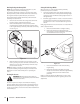
4. Attach the hose coupler to the water port on your decks surface. See Fig. 6-2. Lubrication Warning! Before lubricating, repairing, or inspecting, always disengage PTO, set parking brake, stop engine and remove key to prevent unintended starting. Front Wheels Each of the front wheel axles and rims is equipped with a grease fitting. See Fig. 6-3. Lubricate with a No. 2 multi-purpose grease applied with a grease gun after every 25 hours of tractor operation. Figure 6-2 5. Turn the water on. 6.
Adjustments Leveling the Deck (Side to Side) WARNING! Shut the engine off, remove the ignition key and engage the parking brake before making adjustments. Protect your hands by using heavy gloves when handling the blades. NOTE: Check the tractor’s tire pressure before performing any deck leveling adjustments. Refer to Tires on page 25 for information regarding tire pressure. If the cutting deck appears to be mowing unevenly, a side to side adjustment can be performed. Adjust if necessary as follows: 1.
Steering Adjustment If the tractor turns tighter in one direction than the other, or if the ball joints are being replaced due to damage or wear, the steering drag links may need to be adjusted. Adjust the drag links so that equal lengths of each are threaded into the ball joint on the left side and the ball joint on the right side: 1. Remove the hex nut on the top of ball joint. See Fig. 6-6. Ball Joint Drag Link Hex Nut Figure 6-6 2. Thread the ball joint inward to shorten the drag link.
7 Service Cutting Deck Removal 7. To remove the cutting deck, proceed as follows: Remove the cotter pin from the end of the stabilizer rod and slide the stabilizer out of the hanger bracket on the deck. See Fig. 7-2. Disengage the PTO (Blade Engage) and engage the parking brake. 1. Place the deck gauge wheels in their highest setting (lowest deck setting). 2. Lower the deck by moving the deck lift lever into the bottom notch on the right fender. 3.
3. Continue holding the blade onto the star hub of the spindle, and remove the flange nut and cutting blade. 4. Repeat the previous steps to remove the other blade. 5. To properly sharpen the cutting blades, remove equal amounts of metal from both ends of the blades along the cutting edges, parallel to the trailing edge, at a 25° to 30° angle.
Changing the Timing Belt 8. WARNING! Be sure to shut the engine off, remove ignition key, disconnect the spark plug wire(s) to prevent unintended starting before removing the belt(s). To replace the timing belt, proceed as follows: 1. Remove the deck from beneath the tractor (refer to Cutting Deck Removal). 2. Remove the PTO belt drive pulley of the right hand spindle assembly as described in “Changing the PTO Belt.” 3.
15. If the timing belt was installed correctly and the timing arrows were positioned as shown in Fig. 7-6, the cutting blades should be in the position shown in Fig. 7-7. 6. Sitting in front of the tractor, facing rearward, make certain the belt is not twisted; then reach beneath the tractor to grasp the belt and pull it toward the PTO pulley. NOTE: References to left and right are from the front of the tractor in the following instructions. 90 7.
Battery Fuse California Proposition 65 Warning! Battery posts, terminals, and related accessories contain lead and lead compounds, chemicals known to the State of California to cause cancer and reproductive harm. Wash hands after handling. Caution: If removing the battery, disconnect the NEGATIVE (Black) wire from it’s terminal first, followed by the POSITIVE (Red) wire. When reinstalling the battery, always connect the POSITIVE (Red) wire its terminal first, followed by the NEGATIVE (Black) wire.
8 Troubleshooting Problem Engine fails to start Cause Remedy 1. PTO/Blade Engage lever engaged. 1. Place lever in disengaged (OFF) position. 2. Parking brake not engaged. 2. Engage parking brake. 3. Spark plug wire disconnected. 3. Connect wire to spark plug. 4. Throttle/Choke control lever not in correct starting position. 4. Place Throttle/Choke lever to FAST position. 5. Fuel tank empty, or stale fuel. 5. Fill tank with clean, fresh (less than 30 days old) gas. 6. Blocked fuel line. 6.
9 Replacement Parts Component Part Number and Description 759-3336 Spark Plug (Champion RC12YC) KH-20-883-02-S Air Filter Element KH-20-083-03-S Precleaner Element KH-52-050-02-S Oil Filter KH-25-050-22-S1 Fuel Filter 942-04217 2-in-1 Timing Deck Blade 918-04512A Drive Spindle Assembly 918-04516 Driven Spindle Assembly Phone (800) 965-4CUB to order replacement parts or a complete Parts Manual (have your full model number and serial number ready).
Component Part Number and Description 734-04155 Deck Wheel (Front) 734-0973 Deck Wheel (Rear) 925-1707D Battery 951-3111 Fuel Tank Cap 746-1084 Throttle/Choke Control and Cable 725-2054A Ignition Key (Plastic) 631-04254 Discharge Chute Assembly 954-04167 Timing Belt 754-0266A V-Belt Phone (800) 965-4CUB to order replacement parts or a complete Parts Manual (have your full model number and serial number ready). Parts Manual downloads are also available free of charge at www.cubcadet.com.
10 Attachments & Accessories The following attachments and accessories are compatible for Cub Cadet LTX 1042. See your Cub Cadet dealer or the retailer from which you purchased your tractor for information regarding price and availability. Caution: Cub Cadet Series 1000 lawn tractors are NOT designed for use with any type of ground-engaging attachments (e.g. tiller or moldboard plow). Use of this type of equipment WILL void the tractor’s warranty.
Notes 11 33
CALIFORNIA EMISSION CONTROL WARRANTY STATEMENT YOUR WARRANTY RIGHTS AND OBLIGATIONS The California Air Resources Board and MTD Consumer Group Inc are pleased to explain the evaporative emission control system warranty on your 2008 lawn mower. In California, new lawn mowers must be designed, built and equipped to meet the State’s stringent anti-smog standards.
WARRANTED PARTS: The repair or replacement of any warranted part otherwise eligible for warranty coverage may be excluded from such warranty coverage if MTD Consumer Group Inc demonstrates that the lawn mower has been abused, neglected, or improperly maintained, and that such abuse, neglect, or improper maintenance was the direct cause of the need for repair or replacement of the part.
CUB CADET LLC MANUFACTURER’S LIMITED WARRANTY FOR SERIES 1000 & SERIES 1500 TRACTORS IMPORTANT: To obtain warranty coverage owner must present an original proof of purchase and applicable maintenance records to the servicing dealer. Please see the operator’s manual for information on required maintenance and service intervals. In the U.S.A.: Check your Yellow Pages, or contact Cub Cadet LLC at P.O. Box 361131, Cleveland, Ohio 44136-0019, call 1-877-282- 8684 or log on to our website at www.cubcadet.com.