Operator's Manual Model IMPORTANT: CC 3075 READ SAFETY RULES AND INSTRUCTIONS P/N 769-00876 (10/03) PRINTED IN USA CAREFULLY
Table of Contents Content Page Section 1: Safety ........................................................... Section 2: Know Your Unit ................................................... 3 6 Section 3: Assembly ........................................................ Section 4: Oil and Fuel ...................................................... 7 8 Section 5: Operation .................................................. Section 6: Maintenance .....................................................
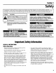
Section 1 Safety The purpose of safety symbols is to attract your attention to possible dangers. The safety symbols, and the r explanations, deserve your careful attention and understanding. The safety warnings do not by themselves eliminate ] | any danger. The instructions or warnings they give are not substitutes for proper accident prevention measures. / SYMBOL _1_ ,AI, MEANING ] I SAFETY ALERT SYMBOL: Indicates danger, I warning or caution.
Safet) Safety Warnings for Gas Trimmers • Use the right toot. Only use this tool for the purpose intended. • Do not overreach. Always keep proper footing and balance. Gasoline is highly flammable, and its vapors can explode if ignited. Take the following precautions. • Store fuel only in containers specificalIy designed and approved for the storage of such materials. • Always stop the engine and allow it to cool before filIing the fuel tank.
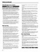
Safety and International Symbols lhis operator's manuaI describes safety and international symbols and pictographs that may appear on this product. Read the operator's manual for complete safety, assembly, operating and maintenance and repair information. SYMBOL MEANING SYMBOL • SAFETY ALERT SYMBOL indicates danger, warning, or caution. May be used in conjunction with other symbols or pictographs.
Section 2 KnowYourUnit Applications With the optional brushcutter accessory kit: As a trimmer: Cutting weeds and light bush of up to 1/2 inch in diameter Cutting grass and light weeds Spark Plug. Edging Starter Rope Grip / Decorative trimming around trees, fences, etc. Fuel Cap Throttle Control Support Fitting ......
Section 3 Assembly Install and Adjust the D-handle Shaft Grip (4) Screws =_ Shaft Housing _ _1_ == == 1. Remove the screws and bottom ciamp piece that were installed on the D-handle for shipping. 2. Place D-handle over the shaft housing and onto the bottom clamp (Fig. 3-1). Place it a minimum of 6 inches (15.24 cm) from the end of the shaft grip. 3. Start screws with a large Fiat-head or T-25 Torx screwdriver. Do not tighten until you make the handle adjustment. 4.
Section 4 Oiland Fuel For proper engine operation and maximum reliability, pay strict attention to the oil and fuel mixing instructions on the 2-cycle oil container. Using improperly mixed fuel can severely damage the engine. UNLEADED GAS ° i GALLON US MIXING RATIO 2 C¥CI-E OI13i2 FL OZ (95 _i1 Thoroughly mix the proper ratio of 2-cycle engine oil with unleaded gasoline in a separate fuel can. Use a 40:1 fuel/oit ratio. Do not mix them directly in the engine fuet tank.
Section 5 Operation P)iii OperateithisunitQn_inawe!!_venti!atedo_doQrar_i carbonmonoxideexhaustfumescanbelethal;ina c_nfinediiareaiiiiiiiiiiiiiiiiiiiiiiiiiiiiiiiiiiiiiiiiiiiiiiiiiiiiiiiiiiiiiiiiiiiiiiiiiiiiiiiiiiiiiiiiiiiiiiiiiiiiiiiiiiiiiiiiiiiiiiiiiiiiiiiiiiiiiiiiiiiiiiiiiiiiiiiii m _ w On/Off Avoid ac_idental startingi Make sure you are in the S_rting positi_n when puiiing the sta_er rope (Figi s_3) i To avoid serious injury, the operator and unit must be inastable poSit iO_ Whiie start in9 Make SU
Operation(continued) Read and understand the operator's each add-on prior to operation. manual for Removing the Cutting Attachment or Add-0ns 1. [urn the knob counterclockwise to loosen (Fig. 5-4). 2. Press and hold the release button (Fig. 5-4). 3. While firmly holding the upper shaft housing, puil the cutting attachment or add-on straight out of the EZ-Link _Mcoupier (Fig. 5-5}.
Operation(continued) Each time the head is bumped, about 1 inch (25.4 mm) of trimming line releases. A blade in the cutting attachment shield wiii cut the line to the proper length if any excess line is released. For best resuIts, tap the bump knob on bare ground or hard soil. If you attempt a tine release in tail grass, the engine may stall. Always keep the trimming line fully extended. Line release becomes more difficult when the cutting line gets shorter.
Section 6 Maintenance Maintenance Schedule Perform these required maintenance procedures at the frequency statedin the table, lhese procedures should also be a part of any seasonal tune-up. NOTE: Some maintenance procedures may require special tools or skills. If you are unsure about these procedures take your unit to any nonroad engine repair establishment. To prevent serious injury, never perform maintenance or repairs with unit running. Always service and repair a cool unit.
Maintenance (continued) Winding the Existing Inner Reel Indexing Teeth 1. Hold the outer spooi with one hand and unscrew the Bump Knob clockwise (Fig. 6-1). Inspect the bolt inside the Bump Knob to make sure it moves freety. Replace the Bump Knob if damaged. 2. Remove the inner reel from the outer spool (Fig. 6-1). 3. Remove spring from the inner reel (Fig. 6-1). 4. Use a clean cloth to clean the the inner reel, spring, shaft, and inner surface of the outer spool. 5.
Maintenance (continued) 12. insert the ends of the Iine into the two holding slots (Fig. 6-7). 13. insert the ends of the iine through the eyelets in the outer spooi and piace inner reel with spring inside the outer spooi (Fig. 6-8). Push the inner reet and outer spool together. While holding the inner reel and outer spooI, grasp the ends and pull firmty to release the line from the holding slots in the reel. NOTE: The spring must be assembled on the inner reel before reassembling the cutting attachment.
Maintenance (continued) Air Filter Maintenance Cleaningthe Air Filter Carburetor/Air Filter Cover To avoid serious personal injury, always turn your trimmer off and allow it to cool before you clean or service it. Clean and re-oit the air filter every 10 hours of operation. It is an important item to maintain. Failure to maintain the air filter will VOID the warranty. Tab 1. Fig. 6-9 2, Remove the carburetor/air filter cover by pushing on the tab on top of the cover (Fig. 6-9).
Maintenance (continued) Check Fuel Mixture Otd and/or improperly mixed fuel is usualIy the reason for improper unit performance. Drain and refitl the tank with fresh, properly mixed fuet prior to making any adjustments. Refer to Oil and Fuel Information, Clean Air Filter The condition of the air filter is important to the operation of the unit. A dirty air filter will restrict air ftow and change the air/fuel mixture.
Maintenance (continued) Storage • Never store the unit with fuet in the tank where fumes may reach an open flame or spark. • Atlow the engine to cool before storing. • Store the unit locked up to prevent unauthorized use or damage. V • Store the unit in a dry, welt-ventilated Fig. 6-15 area. • Store the unit out of the reach of children. Replacingthe Spark Plug Long Term Storage Use a Champion RC.J6Y spark plug (or equivalent). 1he correct air gap is 0.025 inch (0.
Section 7 Troubleshooting CAUSE ACTION On/Off stop control is in the OFF position Turn the on/off stop control to ON Empty fuel tank Fill fuel tank with properly mixed fuel Primer bulb wasn't pressed enough Press primer bulb fully and siowiy 10 times Engine is flooded Squeeze the trigger, put lever in Position 2 and pull the starter rope Old or improperly mixed fuel Drain gas tank and add fresh fuel mixture Fouled spark plug Replace or clean the spark plug Plugged spark arrestor Clean or rep
Section 8 Specifications Engine Fype .......................................................................................................................................... Air-Cooled, 2-Cycle Stroke .................................................................................................................................................... 1.25 in. (31.75 mm) Displacement ..............................................................................................................................
Notes zoiiiiiiiiiiii
Notes ZZiiiiiii
EPA Emission Control Warranty Statement Your Warranty Rights and Obligations The EnvironmentaI Protection Agency and Cub Cadet LLC (Cub Cadet) are pteased to explain the emission control system warranty on your 2002 and later small off-road engine. New smalI off-road engines must be designed, built and equipped to meet stringent anti-smog standards.
' ENGINE PARTS - MODEL CC3075 2-CYCLE GAS TRIMMER PPN 41ADC75C010 Item ! 2 3 4 5 6 7 8 9 10 11 12 13 14 Part No.
BOOM AND TRIMMER PARTS - CC3075 2-CYCLE GAS TRIMMER ' PPN 41ADC75C010 Item Part No.
The limited warranty set forth below is given bY Cub Cadet LLC with respect to new merchandise 15urchased and used in the United States, its possessions and territories. Cub Cadet LLC warrants this product against defects in material and workmanship for a period of two (2) years commencing on the date of original purchase and will, at its option, repair or repiaee, free of charge, any part found to be defective in material or workmanship.