Operator's Manual 2-Cycle Trimmer Model CC 2000 IMPORTANT: READ SAFETY RULES AND INSTRUCTIONS CAREFULLY Warning: For users on U.S. Forest Land and in the states of California, Maine, Oregon and Washington. All U.S.
TABLEOF CONTENTS Content Section 1: Salty Page ............................................................ 3 Section 2: Know Your Unit ..................................................... 7 Section 3: Assembly .......................................................... 8 Section 4: Oil and Fuel ........................................................ 9 Section 5: Operation 10 ......................................................... Section 6: Maintenance ......................................
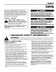
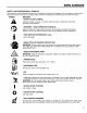
Section 1 Safety The purpose of safety symbols is to attract your attention to possible dangers. The safety symbols, and their explanations, deserve your careful attention and understanding. The safety warnings do not by themselves eliminate any danger. The instructions or warnings they give are not substitutes for proper accident prevention measures. SYMBOL Failure to obey a safety warning will result in serious injury to yourself or to others.
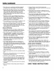
Safety (continued) • Store fuel only in containers specifically designed and approved for the storage of such materials. • Always stop the engine and allow it to cool before filling the fuel tank. Never remove the cap of the fuel tank, or add fuel, when the engine is hot. Never operate the unit without the fuel cap securely in place. Loosen the fuel tank cap slowly to relieve any pressure in the tank. • Add fuel in a clean, well-ventilated area outdoors where there are no sparks or flames.
Safety (continued) SAFETY AND INTERNATIONAL SYMBOLS This operator's manual describes safety and international symbols and pictographs that may appear on this product. Read the operator's manual for complete safety, assembly, operating and maintenance and repair information. SYMBOL MEANING or caution. •Indicates SAFETY danger, ALERT warning, SYMBOL symbols or pictographs.
Safety (continued) SYMBOL MEANING • SHARP BLADE WARNING: Sharp blade on cutting attachment touch line cutting blade. • CHOKE shield. To prevent serious injury, do not CONTROL A • START position. B • RUN position. • DO NOT USE BLADES WARNING: To prevent serious personal unit with any type of blade. injury, do not attach or operate the WARNING: The operation of any power tool can cause foreign objects to be thrown into your eyes. This can lead to severe eye damage.
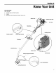
Section 2 KnowYourUnit APPLICATIONS As a trimmer; • Cutting grass and light weeds. • Edging • Decorative trimming around trees, fences, etc. Spark Plug pe Grip _ Fuel Cap Shaft Grip _ Air Filter Cover Throttle Control On/Off Stop Control D-Handle J Shaft Housing Choke Lever Cutting Attachment Shield Primer Bulb Line Cutting Blade \\\ Cutting Attachment 7
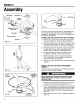
Section 3 Assembly Shaft Grip (4) Screws_ _-_(4) Screws Shaft Housing J Minimum 6 inches (15.24 cm) On some units, the D-handle may be preinstalled and only require loosening the screws and adjusting the D-handle to the operator. Go to step 4 for adjusting the D-handle if preinstalled. D-Handle Bottom Clamp ® (4) Nuts INSTALLING AND ADJUSTING THE D-HANDLE 1. Remove the screws, nuts and bottom clamp piece that were installed on the D-handle for shipping. 2.
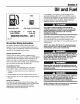
Section 4 Oil and Fuel If unavailable, use a good 2-cycle oil designed for air-cooled engines along with a fuel additive, such as STA-BIL® Gas Stabilizer or an equivalent. Add 0.8 oz. (23 ml) of fuel additive per gallon of fuel according to the instructions on the container. NEVER add fuel additives directly to the unit's fuel tank. UNLEADED GAS 1 US, GALLON (3,8 LITERS) Cub Cadet 2 CYCLE OIL + 4,0 FL, OZ, (118 ml) MIXING RATIO - 32:1 Fig.
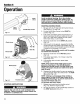
Section 5 Operation J Start/ On (I) \ Stop/ Off (O) \ \ Avoid accidental starting. Be in the starting position whenever pulling the starting rope. To avoid serious personal injury, the operator and unit must be in a stable position while starting. STARTING \ \ INSTRUCTIONS 1. Mix gas with oil. Fill fuel tank with fuel/oil mixture. See Section 4, Oil and Fuel. 2. Put the On/Off Stop Control in the START (I) position (Fig. 5-1). On/Off Stop Control Fig. 5-1 . 4.
Operation (continued) NOTE: Always keep the trimming line fully extended. Line release becomes more difficult as cutting line becomes shorter. Each time the head is bumped, about 1 inch (25.4 mm) of trimming line is released. A blade in the cutting attachment shield will cut the line to the proper length if excess line is released. For best results, tap the Bump Head on bare ground or hard soil. If line release is attempted in tail grass, the engine may stall. Always keep the trimming line fully extended.
Operation(continued) DECORATIVE TRIMMING Decorative trimming is accomplished by removing all vegetation around trees, posts, fences, etc. Rotate the whole unit so that the cutting attachment at a 30 ° angle to the ground (Fig. 5-6). is Fig. 5-6 Section 6 Maintenance NOTE: Some maintenance procedures may require special tools or skills. If you are unsure about these procedures take your unit to an authorized service dealer.
Maintenance (continued) Outer Spool _ Shaft There are two methods to replace the trimming line. • Wind the inner reel with new line • Install a prewound inner reel Inner Reel___ ___ Spring Fig. _ Winding the Existing Inner Reel 1. Hold the outer spool with one hand and unscrew the bump knob counterclockwise (Fig. 6-1). Inspect the bolt inside the bump knob to make sure it moves freely. Replace the bump knob if damaged. 2. Remove the inner reel from the outer spool (Fig. 6-2). 3.
Maintenance (continued) 7. Wind the lines in tight even layers, onto the reel (Fig. 6-6). Wind the line in the direction indicated on the inner reel. Place your index finger between the two lines to stop the lines from overlapping. Do not overlap the ends of the line. Proceed to step 11. Membrane . Line Installation Take approximately 10 feet (3 m) of new trimming line. Insert one end of the line through one of the two holes in the inner reel (Fig. 6-6).
Maintenance (continued) AIR FILTER MAINTENANCE Cleaning the Air Filter To avoid serious personal injury, always turn your trimmer off and allow it to cool before you clean or do any maintenance on it. Carburetor/Air Filter Cover Clean and re-oil the air filter every 10 hours of operation, it is an important item to maintain. Not maintaining the air filter will VOID the warranty. Tab Fig. 6-10 1. Remove the carburetor/air filter cover by pushing on the tab on top of the cover (Fig. 6-10). 2.
Maintenance (continued) 2. Use a needlenose pliers to grasp the collar of the spark arrestor and pull it out of the muffler (Fig. 6-14). Adjust Idle Speed Screw NOTE: Use only a needlenose pliers. Other pliers or tools may damage the spark arrestor. 3. Clean the spark arrestor with a wire brush. Replace if damaged or unable to clean thoroughly. 4. Reinstall spark arrestor. Use the needlenose pliers to gently push the spark arrestor back into the muffler until it snaps into place.
Maintenance (continued) REPLACING THE SPARK PLUG CLEANING Use a Champion RCJ6Y spark plug (or equivalent). The correct air gap is 0.025 inch (0.655 ram). Remove the plug after every 25 hours of operation and check its condition. 1. Stop the engine and allow it to cool. Grasp the plug wire firmly and pull the cap from the spark plug. 2. Clean dirt from around the spark plug. Remove the spark plug from the cylinder head by turning a 5/8 inch socket counterclockwise. 3.
Section 7 Troubleshooting CAUSE ACTION On/Off Stop Control is in STOP position Empty fuel tank Primer bulb wasn't pressed enough Turn On/Off Stop Control to START Fill fuel tank with properly mixed fuel Press primer bulb fully and slowly 5-7 times Engine flooded Use starting procedure with choke lever in the RUN position, Pg.
Section 8 m Specifications Engine Type ..................................................................... Displacement ..................................................................... Air-Cooled, 2-Cycle 1.4 cu. in. (25 cc) Clutch Type ........................................................................... Centrifugal Idle Speed RPM .................................................................... 2,400-3,600 rpm Operating RPM (Trimmer) .................................................
MANUFACTURER'S LIMITED WARRANTY FOR: C bCo.d ' ft The limited warranty set forth below is given by Cub Cadet LLC with respect to new merchandise purchased and used in the United States, its possessions and territories. Cub Cadet LLC warrants this product against defects in material and workmanship for a period of two (2) years commencing on the date of original purchase and will, at its option, repair or replace, free of charge, any part found to be defective in material or workmanship.