
Operator`s manual
Assembly & Set-Up
3
7
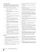
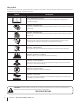
Contents of Carton
• Snow Thrower • Replacement Auger Shear Pins • Chute Assembly
• Flex Shaft • Engine Manual • Product Registration Card
• Snow Thrower Operator’s Manual
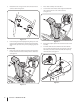
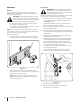
Figure 3-2
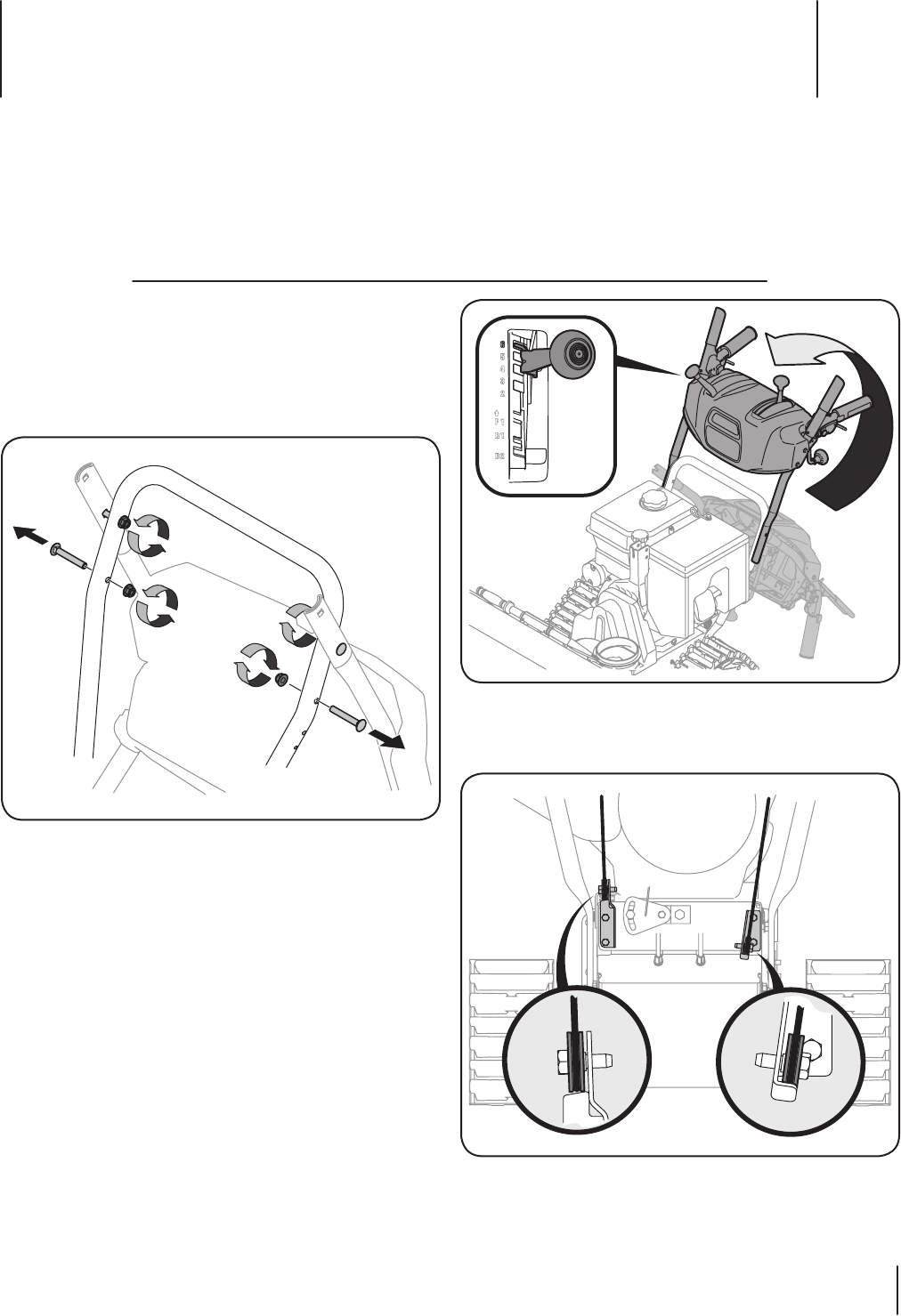
NOTE: Make certain the cables are seated properly in the
roller guides. See Figure 3-3.
Figure 3-3
Assembly
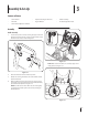
Handle Assembly
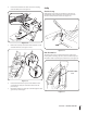
1. Loosen the top two lock nuts securing the upper and lower
handle and remove the two carriage screws from the lower
handle and set aside as shown in Figure 3-1.
Figure 3-1
2. Place the shift lever in the Forward-6 position.
3. Cut zip ties securing flex shaft to the lower handle and set
the flex shaft aside.
4. Remove rubber bands securing cables to carriage screws
and cut zip tie securing shift rod to lower handle. Carefully
pivot the handle upward. See Figure 3-2.
NOTE: You will need to lower shift rod to the side slightly
to manuever the handle panel over it when pivoting the
handle upward.