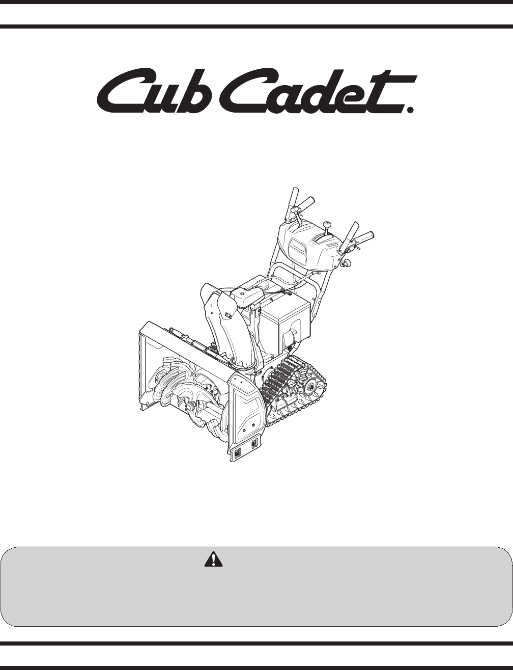
Safe Operation Practices • Set-Up • Operation • Maintenance • Service • Troubleshooting • Warranty Operator’s Manual Three-Stage Snow Thrower — 3X 30” TRAC WARNING READ AND FOLLOW ALL SAFETY RULES AND INSTRUCTIONS IN THIS MANUAL BEFORE ATTEMPTING TO OPERATE THIS MACHINE. FAILURE TO COMPLY WITH THESE INSTRUCTIONS MAY RESULT IN PERSONAL INJURY. CUB CADET LLC, P.O. BOX 361131 CLEVELAND, OHIO 44136-0019 Printed In USA Form No.
1 To The Owner Thank You Thank you for purchasing a Cub Cadet 3X Snow Thrower. It was carefully engineered to provide excellent performance when properly operated and maintained. Please read this entire manual prior to operating the equipment. It instructs you how to safely and easily set up, operate and maintain your machine. Please be sure that you, and any other persons who will operate the machine, carefully follow the recommended safety practices at all times.
Important Safe Operation Practices 2 WARNING! This symbol points out important safety instructions which, if not followed, could endanger the personal safety and/or property of yourself and others. Read and follow all instructions in this manual before attempting to operate this machine. Failure to comply with these instructions may result in personal injury. When you see this symbol.
Safe Handling of Gasoline 5. To avoid personal injury or property damage use extreme care in handling gasoline. Gasoline is extremely flammable and the vapors are explosive. Serious personal injury can occur when gasoline is spilled on yourself or your clothes which can ignite. Wash your skin and change clothes immediately. Never run an engine indoors or in a poorly ventilated area. Engine exhaust contains carbon monoxide, an odorless and deadly gas. 6.
Clearing a Clogged Discharge Chute Hand contact with the rotating impeller inside the discharge chute is the most common cause of injury associated with snow throwers. Never use your hand to clean out the discharge chute. To clear the chute: 1. SHUT THE ENGINE OFF! 2. Wait 10 seconds to be sure the impeller blades have stopped rotating. 3. Always use a clean-out tool, not your hands. Maintenance & Storage 1. Never tamper with safety devices. Check their proper operation regularly.
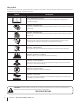
Safety Symbols This page depicts and describes safety symbols that may appear on this product. Read, understand, and follow all instructions on the machine before attempting to assemble and operate. Symbol Description READ THE OPERATOR’S MANUAL(S) Read, understand, and follow all instructions in the manual(s) before attempting to assemble and operate WARNING— ROTATING BLADES Keep hands out of inlet and discharge openings while machine is running.
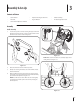
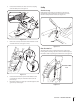
3 Assembly & Set-Up Contents of Carton • Snow Thrower • Replacement Auger Shear Pins • Chute Assembly • Flex Shaft • Engine Manual • Product Registration Card • Snow Thrower Operator’s Manual Assembly Handle Assembly 1. Loosen the top two lock nuts securing the upper and lower handle and remove the two carriage screws from the lower handle and set aside as shown in Figure 3-1. Figure 3-2 NOTE: Make certain the cables are seated properly in the roller guides. See Figure 3-3. Figure 3-1 2.
5. Reattach the two carriage screws and lock nuts removed earlier as shown in Figure 3-4. 2. Place chute assembly onto chute base. 3. Secure chute control head to chute support bracket with the lock nuts and hex screws removed earlier. See Figure 3-6. 4. Remove the hairpin clip from the rear of the chute control assembly. 5. Insert flex shaft removed earlier from the lower handle into rear of the chute directional control head.
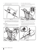
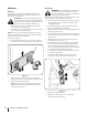
6. Insert the flex shaft into the chute control rod coupling under the dash panel. See Figure 3-8. Set-Up Shear Pins Storage Replacement auger shear pins and bow tie cotter pins are included with your snow thrower. Store them in your snow thrower’s dash panel until needed. See Figure 3-10. Figure 3-8 7. Remove the cotter pin and washer from the ferrule on the end of the shift rod. See Figure 3-9 inset.
Adjustments Auger Control WARNING! Prior to operating your snow thrower, carefully read and follow all instructions below. Perform all adjustments to verify your snow thrower is operating safely and properly. Skid Shoes The snow thrower skid shoes are adjusted at the factory for shipping purposes. Adjust them downward, if desired, prior to operating the snow thrower.
4 Controls and Features Shift Lever Two-Way Chute-Pitch Control Drive Control Auger Control Headlight Heated Grips Chute Assembly Steering Trigger Control Clean Out Tool Overhead Chute Directional Control Augers Skid Shoe Figure 4-1 Snow thrower controls and features are described below and illustrated in Figure 4-1. Shift Lever The shift lever is located in the right side of the handle panel and is used to determine ground speed and direction of travel. Forward There are six forward (F) speeds.
Auger Control Steering Trigger Controls The auger control is located on the left handle. Squeeze the control grip against the handle to engage the augers and start snow throwing action. Release to stop. Drive Control / Auger Clutch Lock The left and right wheel steering trigger controls are located on the underside of the handles. • Squeeze the right control to turn right. • Squeeze the left control to turn left.
Track Lock Lever The track lock lever is located on the right side of the snow thrower and is used to select the position of the auger housing and the method of track operation. Move the lever to the right, then forward or rearward to one of the four positions. Transport Raises the snow thrower auger housing for easy transport. Snow-covered Gravel Raises the snow thrower auger housing so that its shave plate leaves gravel undisturbed while clearing snow.
5 Operation Starting and Stopping the Engine Replacing Shear Pins Refer to the Engine Operator’s Manual packed with your snow thrower for instructions on starting and stopping the engine. The augers are secured to the spiral shaft with shear pins and cotter pins. If the auger should strike a foreign object or ice jam, the snow thrower is designed so that the pins may shear. If the augers will not turn, check to see if the pins have sheared. See Figure 5-2. To Engage Track Drive 1.
6 Maintenance & Adjustments Maintenance 4. Engine Slide the shave plate downward into the second position. Reinstall and tighten all bolts securely. See Figure 6-2. Refer to the Engine Operator’s Manual. Shave Plate and Skid Shoes The shave plate and skid shoes on the bottom of the snow thrower are subject to wear. They should be checked periodically and replaced when necessary. NOTE: The skid shoes on this machine have two wear edges.
Lubrication Wheels At least once a season, remove both wheels. Clean and coat the axles with a multipurpose automotive grease before reinstalling wheels. Auger Shaft At least once a season, remove the shear pins from the auger shafts. Spray lubricant inside the shafts and around the spacers and the flange bearings/bushings found at either end of the shafts. See Figure 6-4. Figure 6-5 4. Apply a light coating of Bostik Regular Grade Never-Seez® to the hex shaft. See Figure 6-6.
Adjustments 5. Shift Rod If the full range of speeds (forward and reverse) cannot be achieved, adjust the shift rod as follows: 1. Place the shift lever in the fastest forward speed position. 2. Remove the cotter pin and washer from the adjustment ferrule on the shift rod and pull it out from the shift lever. See Figure 6-7. Insert the ferrule into the upper hole and secure with the washer and cotter pin.
3. Position the bracket upward to provide more slack (or downward to increase cable tension). 4. Retighten the upper hex screw. 5. Check the adjustment of the drive control as described above to verify proper adjustment has been achieved as follows: a. With the drive control released, move the shift lever back and forth between the R2 position and the F6 position several times. There should be no resistance in the shift lever.
7 Service Belt Replacement 3. Auger Belt Loosen and remove the two bolts and flat washers securing the belt guide. See Figure 7-2. Remove belt guide. To remove and replace your snow thrower’s auger belt, proceed as follows: 1. Allow the engine to run until it is out of fuel. Do not attempt to pour fuel from the engine. 2. Remove the plastic belt cover on the front of the engine by removing the two self-tapping screws. See Figure 7-1. Figure 7-2 4. Roll the auger belt off the engine pulley.
5. Carefully pivot the snow thrower up and forward so that it rests on the auger housing. 6. Remove the frame cover from the underside of the snow thrower by removing the self-tapping screws which secure it. See Figure 7-4. NOTE: Engaging the auger control will ease removal and reinstallation of the belt. Figure 7-6 9. Figure 7-4 7. Replace the auger belt by following instructions in reverse order.
8 Troubleshooting Problem Engine fails to start Cause Remedy 1. Fuel tank empty, or stale fuel. 1. Fill tank with clean, fresh gasoline. Fuel becomes stale after thirty days. 2. Blocked fuel line. 2. Clean the fuel line. 3. Choke not in the RUN position. 3. Move choke control to RUN position 4. Faulty spark plug. 4. Clean, adjust gap or replace. 5. Key not in ignition switch on engine. 5. Insert the key fully into the switch. 6. Spark plug wire disconnected. 6. Connect spark plug wire. 7.
9 Replacement Parts Component Part Number and Description 954-04195A 954-05019 Auger Drive Belt Track Drive Belt 684-04153C 935-04054 Friction Wheel Assembly Friction Wheel Rubber 925-1629 Lamp, 12V 738-04124A 714-04040 Shear Pin, 1.
10 Attachments & Accessories The following attachments and accessories are available for your Cub Cadet snow thrower. See your Cub Cadet dealer or the retailer from which you purchased your snow thrower for information regarding price and availability.
CUB CADET LLC MANUFACTURER’S LIMITED WARRANTY FOR SNOW THROWERS, LOG SPLITTERS CHIPPER-SHREDDERS, CHIPPER-SHREDDER VACUUMS AND JET SWEEPS The limited warranty set forth below is given by Cub Cadet LLC with respect to new merchandise purchased and used in the United States, its possessions and territories, and by MTD Products Limited with respect to new merchandise purchased and used in Canada and/or its territories and possessions. a.