Safety • Assembly • Operation • Tips & Techniques • Maintenance • Troubleshooting • Parts Lists • Warranty OPERATOR’S MANUAL Series 3000 Tractor — Model GT 3200 IMPORTANT READ SAFETY RULES AND INSTRUCTIONS CAREFULLY BEFORE OPERATION Warning: This unit is equipped with an internal combustion engine and should not be used on or near any unimproved forest-covered, brush-covered or grass-covered land unless the engine’s exhaust system is equipped with a spark arrester meeting applicable local or state laws (
Section 1: To the Owner Thank You frequently to familiarize yourself with the machine, its features and operation. Cub Cadet LLC reserves the right to change product specifications, designs and equipment without notice and without incurring obligation. This product meets the rigid safety standards of the Outdoor Power Equipment Institute and an independent testing laboratory. If you have any problems or questions concerning the machine, phone your local Cub Cadet dealer or contact us directly.
Section 2: Important Safe Operation Practices WARNING: This symbol points out important safety instructions which, if not followed, could endanger the personal safety and/or property of yourself and others. Read and follow all instructions in this manual before attempting to operate this machine. Failure to comply with these instructions may result in personal injury. When you see this symbol.
11. Do not put hands or feet near rotating parts or under the cutting deck. Contact with the blade(s) can amputate hands and feet. 12. A missing or damaged discharge cover can cause blade contact or thrown object injuries. 1 . Stop the blade(s) when crossing gravel drives, walks, or roads and while not cutting grass. 14. Watch for traffic when operating near or crossing roadways. This machine is not intended for use on any public roadway. 15.
. Use slow speed. Choose a low enough speed setting so that you will not have to stop or shift while on the slope. Tires may lose traction on slopes even though the brakes are functioning properly. Always keep machine in gear when going down slopes to take advantage of engine braking action. 4. Follow the manufacturer’s recommendations for wheel weights or counterweights to improve stability. 5. Use extra care with grass catchers or other attachments. These can change the stability of the machine. 6.
Towing 1. Tow only with a machine that has a hitch designed for towing. Do not attach towed equipment except at the hitch point. 2. Follow the manufacturers recommendation for weight limits for towed equipment and towing on slopes. . Never allow children or others in or on towed equipment. 4. On slopes, the weight of the towed equipment may cause loss of traction and loss of control. 5. Travel slowly and allow extra distance to stop. 6. Do not shift to neutral and coast downhill.
6. 7. . 9. 10. 11. 12. 1 . 14. the original equipment manufacturer’s (O.E.M.) blade(s) only, listed in this manual. “Use of parts which do not meet the original equipment specifications may lead to improper performance and compromise safety!” Mower blades are sharp. Wrap the blade or wear gloves, and use extra caution when servicing them. Keep all nuts, bolts, and screws tight to be sure the equipment is in safe working condition. Never tamper with the safety interlock system or other safety devices.
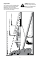
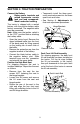
Slope Guide WARNING: Do not mow on inclines with a slope in excess of 15 degrees (a rise of approximately 2-1/2 feet every 10 feet). Use this page as a guide to determine slopes where you may not operate safely. Do not operate your tractor on such slopes. e) long dotte d line (repr esent s a 15 ˚ slop or a fence post 15˚ Fold a Sight and hold this level with a vertical tree... or a corner of a building... Operate Garden Tractors up and down slopes, never across the face of slopes.
SECTION 3: TRACTOR PREPARATION Connect the Battery Battery posts, terminals and related accessories contain lead and lead compounds. Wash hands after handling. • Temporarily install the three previously removed screws into the three open front seat holes. • See Section 8: Adjustments for final seat adjustment procedures. The tractor is shipped with a sealed battery, with the positive battery cable factory connected. The negative cable must be connected.
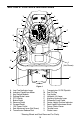
SECTION 4: CONTROLS and FEATURES B A V C U D T E F S Q R P G H I O N J (Not Shown) M K L Figure 1 A B C D E F G H I J K Low Fuel Indicator Lamp Indicator Panel/Hour Meter Key Switch Module Parking Brake Lever PTO Switch Brake Pedal Reverse Pedal Forward Pedal 12V Power Outlet Seat Adjustment Lever (Not Shown) Transmission Release Rod L M N O P Q R S T U V Transmission Oil Fill/Dipstick Fuel Fill Cap Cup Holder Hydraulic Lift Lever Auxiliary Hydraulic Lever Differential Lock Pedal Center Heigh
NOTE: References to LEFT and PTO Engaged Indicator • This indicator illuminates when the key switch is turned to the "Start" position while the PTO switch is pulled outward in the "Engaged" position. Check this indicator if the engine will not crank with the key switch in the "Start" position. If necessary, move the PTO switch to the "Disengaged" position. RIGHT indicate that side of the tractor when facing forward while seated in the drivers seat.
lock circuits are activated and the blades (PTO) will disengage when the tractor is driven in the reverse direction. • Start — Energizes the starter motor to crank and start the tractor engine. Release the key as soon as the engine starts and the key will return to “NORMAL MOWING” position. NOTE: A record of the actual hours of operation should be kept to assure maintenance procedures are completed according to the schedule in this manual.
H. Forward Pedal D. Parking Brake Lever Figure 4 The parking brake lever is located to the right of the steering wheel in the dash panel. With the brake pedal depressed fully, push the parking brake lever downward and release the brake pedal to lock the parking brake. Figure 7 The forward control pedal is located on the right running board below the brake pedal. Slowly press down on the pedal to start moving forward.
M. Fuel Fill Cap The fuel fill cap is located on the fender to the left of the seat. LOWER N. Cup Holder The cup holder is located on the fender to the left of the seat. RAISE O. Hydraulic Lift Lever The hydraulic lift lever is located on the fender to the left of the seat. This lever is used to operate the tractor’s center lift system. Height Adjustment Knob Figure 8 P. Auxiliary Hydraulic Lever The auxiliary hydraulic lever is located on the left fender.
IMPORTANT: When using power take-off operated equipment, best performance is achieved with the throttle lever in the “FAST” position. V. Choke Lever The choke lever is located to the left of the steering wheel in the throttle/choke lever pod. Push the lever forward to close the engine choke plate. SECTION 5: OPERATION Safety Interlock Switches This tractor is equipped with a safety interlock system for the protection of the operator.
continuously for more than 10 seconds at a time. If the engine does not start within this time, turn the key to “STOP” and wait a minute to allow the engine’s starter motor to cool. Try again after waiting. motion. Use the brake pedal to bring the tractor to a stop before depressing either the forward or reverse control pedal. • After the engine starts, slowly release the brake pedal. As the engine warms up, gradually pull the choke lever all the way back.
Driving On Slopes Refer to the SLOPE GAUGE on page 8 to help determine slopes where you may not operate safely. Auxiliary Hydraulics The tractor auxiliary hydraulic circuit consists of two hydraulic outlets with male and female quick connect couplers. The outlets are located beneath the front of the left running board, and are normally used for connecting the optional Hydraulic Front Hitch Kit. The auxiliary hydraulic lever on the left fender controls the oil flow through the auxiliary hydraulic circuit.
Using the REVERSE CAUTION MODE key position (Yellow) position of the key switch module. Refer to Figure 10. The REVERSE CAUTION MODE position of the key switch module allows the machine to be operated in reverse with the blades (PTO) engaged. 3. IMPORTANT: Mowing in reverse is not recommended. Use extreme caution while operating the tractor in the “Reverse Caution Mode”. Always look down and behind before and while backing. Do not operate the tractor when children or others are around.
Engaging Differential Lock Fully depress the diff. lock pedal to lock the transmission differential and provide constant power to both rear wheels when increased traction is needed. Release the diff. lock pedal when extra traction is not needed. Depressing the brake pedal also actuates the diff. lock pedal, resulting in optimal braking action. NOTE: Because of the load on the internal engagement mechanism, releasing the diff. lock pedal may not always disengage the differential lock.
SECTION 6: ADJUSTMENTS and MAINTENANCE Brake Inspection and Adjustment Seat Adjustment WARNING: Do not adjust During normal operation, the tractor brake is subject to minimal wear. However, the brake should be periodically tested, and adjusted if necessary. the seat when the tractor is moving, as this could cause the operator to lose control of the tractor. For the comfort of the operator, the tractor is equipped with an easy to operate adjustable seat.
side panel from the slots of the grille/side panel mounting strip. If greater access is required, the tractor is equipped with quick release side panels. Remove the quick release side panels as follows (See Figure 16): To reinstall the side panels: • Insert the side panel front tabs into the slots of the grille/side panel mounting strip. • Swing the rear of the side panel inward and align so that the tabs of the quick release fasteners go through the side panel slots.
battery. A fully charged battery will store longer in cold temperatures than hot. • Recharge the battery before returning to service. Although the tractor may start, the engine charging system may not fully recharge the battery. Tire Inflation Keep the tires inflated to the recommended pressure. Improper inflation will affect tire life and operator comfort, and also could affect the level of the mower deck and quality of cut. See the tire side wall for proper inflation range.
Grease front wheel bearings • Grease L/R steering knuckles Grease front pivot axle Check engine oil level Change engine oil and filter Check spark plug condition • • Check transmission oil level Change transmission oil filter Change transmission oil Check air cleaner & housing Clean & re-oil foam air pre-cleaner Change air cleaner paper cartridge 300 Hours 250 Hours 200 Hours 150 Hours 100 Hours 50 Hours 10 Hours Operation to be performed Each Use Maintenance Chart • • • • • • • • • • •
Lubrication Illustration Transmission Figure 16 24 L/R Front Wheels Foot Control Pivot Points Engine Oil Can (High quality lubricating oil) Front Pivot Axle Engine Oil: See Figure 27 on page 34 Transmission Oil - Cub Cadet Drive System Fluid Plus - ONLY L/R Steering Knuckle Cub Cadet 251H EP Grease or equivalent No.
SECTION 7: SERVICE The battery is located under the dash panel in the frame pedestal. General Battery Information To remove the battery: • Open the tractor hood by lifting it at the notches in the side panels. • Remove the upper bulkhead baffle from the front of the dash panel by lifting upward on the baffle locking tab on each side. • Pull the upper end of the rubber battery strap rearward to unhook it from the tab on the pedestal.
Headlight Bulb Replacement Replace headlight bulbs as follows: (See Figure 17) 1. After noting which wire connects to each terminal, unplug the wire harness leads from the headlight socket terminals. 2. Rotate the socket assembly as follows to remove from the reflector housing: Socket Tab Adding Transmission Oil WARNING: The fluid for your transmission has been specially formulated to ensure the safe and proper operation of your tractor. Add Cub Cadet Drive System Fluid Plus ONLY.
Changing Transmission Oil WARNING: The fluid for your transmission has been specially formulated to ensure the safe and proper operation of your tractor. When changing the transmission fluid replace it with Cub Cadet Drive System Fluid Plus ONLY. Failure to use Cub Cadet Drive System Fluid Plus may result in a failure of the drive system which could result in property damage or personal injury.
Electrical Box The electrical box contains the relay and fuses. Refer to Figure 19 for the electrical box layout. The electrical box is located under the upper air baffle in front of the dash panel. To access the electrical box: • Raise the hood of the tractor • Locate the locking tabs on the left and right side of the upper air baffle. • Pull up on the locking tabs on each side of the upper air baffle, and remove the upper air baffle from the lower air baffle. Lift the upper air baffle from the tractor.
From just above the right axle carrier, inside the right frame rail, slowly turn the hex nylon lock nut at the end of the brake rod as follows to adjust the brake (Refer to Figure 23): • Turn the nylon lock nut clockwise to increase the braking force. • Turn the nylon lock nut counterclockwise to decrease the braking force. The oil filter should be changed at every oil change interval. The filters can be obtained through your Cub Cadet dealer.
• Pinch in the lock tabs on the oil drain valve, then pull the drain port outward to begin draining oil. Refer to Figure 24. • Fill the fuel tank with treated fuel and run the engine for 2-3 minutes to get stabilized fuel into the carburetor. • After the oil has finished draining, push the end of the oil drain valve back in, until the tabs click into place. Re-cap the end of the oil drain valve to keep debris from entering the drain port. 2.
SECTION 8: ENGINE INFORMATION KOHLER CO. FEDERAL AND CALIFORNIA EMISSION CONTROL SYSTEMS LIMITED WARRANTY SMALL OFF-ROAD EQUIPMENT ENGINES The U.S. Environmental Protection Agency (EPA), the California Air Resources Board (CARB), and Kohler Co. are pleased to explain the Federal and California Emission Control Systems Warranty on your off-road equipment engine.
LIMITATIONS This Emission Control System Warranty shall not cover any of the following: (a) repair or replacement required because of misuse or neglect, improper maintenance, repairs improperly performed or replacement not conforming to Kohler Co. specifications that adversely affect performance and/or durability, and alterations or modifications not recommended or approved in writing by Kohler Co.
Cleaning The Engine Before checking the oil level, clean the area around the oil level dipstick to prevent debris from entering the crankcase. Refer to Figure 26. Always keep the oil level between the “FULL” and the “ADD” marks on the dipstick. See Figure 25. This tractor has an air-cooled engine. Air must be able to circulate freely around the engine through the flywheel screen, through the cooling shrouds and over the fins of the cylinder head and cylinder block.
Changing Engine Oil Dipstick Oil Fill Cap WARNING: If the tractor has recently been operated, the engine and surrounding areas may be hot. Use caution not to burn yourself when working around the engine. See Replacement Parts for the correct oil filter part number. Refer to the below viscosity chart for the proper type of oil to use. Figure 26 Refer to Figure 27 for information regarding the proper type of oil to add to the crankcase. • Place the tractor on a level surface and engage the parking brake.
Changing Fuel Filter • Remove the flexible tubing from the drain valve. Clean the tubing and store in a safe place for future use. WARNING: Do not replace fuel filter when engine is hot. • Clean the drain valve and push the plastic dust cap onto the valve. The engine is equipped with an in-line fuel filter. Visually inspect the filter periodically for a build-up of residue inside the filter body, and for a dirty element which can be indicated by discoloration. Replace the fuel filter when dirty.
WARNING: Operating the engine with loose or damaged air cleaner components will allow unfiltered air into the carburetor, causing extensive wear and eventual failure of the engine. • Clean the area around the element to prevent debris from getting into the engine when the element is removed. • Loosen and remove the element cover wing nut. • Remove the air filter element and element cover by lifting straight up. • Do not wash the paper element or use pressurized air, as this will damage the element.
SECTION 9: TROUBLE SHOOTING Possible Cause Possible Remedy Hard To Start No fuel in fuel tank or carburetor Fuel line or carburetor clogged Fuel filter plugged Water in fuel Choked improperly. Flooded engine Defective ignition or loose wiring Defective battery Spark plug dirty or improperly gapped Fill the tank with fuel. Check the fuel line, carburetor and fuel filter. Clean the fuel line and carburetor with a commercial carburetor cleaner. Replace Drain the fuel tank and carburetor.
Possible Cause Brake dragging Possible Remedy Adjust the brakes. Refer to “ADJUSTMENTS.” Insufficient cooling air-dirt or debris clogging Keep the air intake area, side panels, grille, air intake screen • shrouds • cooling fins • dash intake screen and cooling fins clean. side panels • dash intake screen • or grille Refer to “MAINTENANCE.” Oil level incorrect Engine oil level must not be over the “FULL” mark or below the “ADD” mark on dipstick. Refer to “MAINTENANCE.
SECTION 11: SPECIFICATIONS Engine Manufacturer . . . . . . . . . . . . . . . . . . . . . . . . . . . . . . . . . . . . . . . . . Kohler Horsepower . . . . . . . . . . . . . . . . . . . . . . . . . . . . . . . . . . . . . . . . . . . . . 25 Cylinders . . . . . . . . . . . . . . . . . . . . . . . . . . . . . . . . . . . . . . 2 (Command) Cooling . . . . . . . . . . . . . . . . . . . . . . . . . . . . . . . . . . . . . . . . . . . . . . . . Air Fast Idle Speed . . . . . . . . . . . . . . . . . . . . . . . . .
SECTION 12: Replacement Parts Description Part Number Engine Oil 737-3030A (10W30) 737-3049 (5W30) Air Filter CARTRIDGE FOAM PRE-CLEANER Order KH-24-883-03-S1 Air Filter Assembly Engine Oil Filter KH-12-050-01-S Spark Plug 759-3336 Transmission Oil Cub Cadet Drive System Fluid Plus 737-3120 - Quart 737-3121 - Gallon Transmission Oil Filter 923-3014 Mower Deck Blades 44” Deck -759-3939 (3) 54” Deck -759-3820 (3) 50” Deck -759-04047 (3) 60” Deck -759-3809 (3) Mower Deck Belts 44” Deck - 954-3098
CALIFORNIA EMISSION CONTROL WARRANTY STATEMENT YOUR WARRANTY RIGHTS AND OBLIGATIONS The California Air Resources Board and MTD Consumer Group Inc are pleased to explain the evaporative emission control system warranty on your 2007 lawn mower. In California, new lawn mower must be designed, built and equipped to meet the State’s stringent antismog standards.
2. Any warranted part that is scheduled only for regular inspection in the written instructions supplied is warranted for the warranty period stated above. Any such part repaired or replaced under warranty will be warranted for the remaining warranty period. 3. Any warranted part that is scheduled for replacement as required maintenance in the written instructions supplied is warranted for the period of time before the first scheduled replacement date for that part.
CUB CADET LLC MANUFACTURER’S LIMITED WARRANTY FOR SERIES 3000 TRACTORS IMPORTANT: To obtain warranty coverage owner must present an original proof of purchase and applicable maintenance records to the servicing dealer. Please see the operator’s manual for information on required maintenance and service intervals.
In the U.S.A.: Check your Yellow Pages, or contact Cub Cadet LLC at P.O. Box 361131, Cleveland, Ohio 44136-0019, call 1-877-282- 8684 or log on to our website at www.cubcadet.com. In Canada: Contact MTD Products Limited, Kitchener, ON N2G 4J1, call 1-800-668-1238 or log on to our website at www.mtdcanada.com. Without limiting the foregoing, this limited warranty does not provide coverage in the following cases: a.