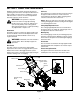
Operator’s Manual 21” Self-Propelled Mower Model 997 IMPORTANT: Read safety rules and instructions carefully Warning: This unit is equipped with an internal combustion engine and should not be used on or near any unimproved forest-covered, brush-covered or grass-covered land unless the engine’s exhaust system is equipped with a spark arrester meeting applicable local or state laws (if any). If a spark arrester is used, it should be maintained in effective working order by the operator.
TABLE OF CONTENTS Content Important Safe Operation Practices Slope Gauge Assembling Your Lawn Mower Know Your Lawn Mower Operating Your Lawn Mower Making Adjustments Content Maintaining Your Lawn Mower Servicing Your Lawn Mower Off-Season Storage Troubleshooting Illustrated Parts List Warranty Page 3 6 7 9 10 11 Page 13 14 17 18 20 36 FINDING MODEL NUMBER This Operator’s Manual is an important part of your new lawn mower. It will help you assemble, prepare and maintain the unit for best performance.
SECTION 1: IMPORTANT SAFE OPERATION PRACTICES WARNING: This symbol points out important safety instructions which, if not followed, could endanger the personal safety and/or property of yourself and others. Read and follow all instructions in this manual before attempting to operate this machine. Failure to comply with these instructions may result in personal injury. When you see this symbol—HEED ITS WARNING.
16. 17. 18. 19. 20. 21. 22. 23. 3. Do not mow on wet grass. Unstable footing could cause slipping. immediately and the blade will stop rotating within three seconds. Mow in daylight or good artificial light; walk, not run. Stop the blade when crossing gravel drives, walkways or roads. If the equipment should start to vibrate abnormally, stop the engine and check immediately for the cause. Vibration is generally a warning of trouble.
4. Mower blades are sharp and can cut. Wrap the blade or wear gloves, and use extra caution when servicing them. 5. Keep all nuts, bolts, and screws tight to be sure the equipment is in safe working condition. 6. Never tamper with safety devices. Check their proper operation regularly. 7. After striking a foreign object, stop the engine, disconnect the spark plug wire and ground against the engine. Thoroughly inspect the mower for any damage. Repair the damage before starting and operating the mower. 8.
SECTION 2: SLOPE GAUGE Use this page as a guide to determine slopes where you may not operate safely. Do not operate your lawn mower on such slopes. FOL D O N DOT TED SIGHT AND HOLD THIS LEVEL WITH A VERTICAL TREE NG A 15 ° SL OPE OR A FENCE POST A CORNER OF A BUILDING A POWER POLE LINE , RE P R ESE NTI 15° WARNING Do not mow on inclines with a slope in excess of 15 degrees (a rise of approximately 2-1/2 feet every 10 feet). A riding mower could overturn and cause serious injury.
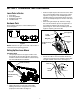
SECTION 3: ASSEMBLING YOUR LAWN MOWER Loose Parts in Carton 1. 2. 3. 4. • Grass Bag Grass Bag Adapter Side Discharge Chute Hardware Pack • Hardware Pack Please identify each piece of the hardware pack as shown in Figure 1. Remove hairpin clip from the outer hole of the weld pin on each handle brackets. Using a pair of pliers, squeeze one leg of the lower handle against the handle bracket. Insert the hairpin clip into the inner hole on the weld pin. Repeat on the other side. See Figure 3.
Attaching Starter Rope • NOTE: Make certain the drive cable is routed around the outside and above the lower handle so it does not interfere with attaching the grass bag. NOTE: The chute door has been designed to move the starter rope out of the way of the bag when the chute door is opened. • • Lift chute door on the grass bag adapter and slide grass bag onto the adapter. See Figure 7. The rope guide, which is connected to the support rod, is located on the right side of the lower handle.
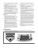
SECTION 4: KNOW YOUR LAWN MOWER Shift Lever Read this operator’s manual and safety rules before operating your lawn mower. Compare the illustration in Figure 9 with your lawn mower to familiarize yourself with the location of various controls and adjustments. Save this manual for future reference. The shift lever is located on the drive control housing on the upper handle. This lever is used to select the forward speed of the mower. When changing speed selection, release the drive clutch lever.
SECTION 5: OPERATING YOUR LAWN MOWER Stopping Engine WARNING: Read, understand, and follow all • instructions and warnings on the machine and in this manual before operating. • NOTE: For shipping purposes your mower is set with the wheels in a low cutting height position. For best results, raise the cutting position until it is determined which height is best for your lawn. See the Adjustment Section for details.
• • • • Attach grass catcher following instructions on page 8 of this manual. Grass clippings will automatically collect in the bag as you run the mower. Operate the mower till the grass bag is full. Stop engine completely by releasing the blade control. Make sure that the unit has come to a complete stop. While holding the grass bag by both the rear handle and the lower handle, lift the grass bag straight up off the adapter. The chute door will move the rope out of the way of the bag.
Drive Control The adjustment wheel is located in the drive control handle housing and is used to tighten or loosen the drive belt. You will have to adjust the drive control if, with the drive control engaged, the mower either does not self-propel or it hesitates. • To resolve the above problems, rotate the adjustment wheel with your fingers: clockwise to tighten the cable and counter-clockwise to loosen the cable. See Figure 12.
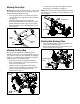
SECTION 7: MAINTAINING YOUR LAWN MOWER • WARNING: Always stop the engine and disconnect the spark plug wire before performing any maintenance work or adjustments on your lawn mower. Cleaning Mower Lubrication The underside of the mower deck should be cleaned after each use to prevent any build-up of debris. If allowed to accumulate, it will cause rust and corrosion. Refer to the lubrication chart in Figure 14.
SECTION 8: SERVICING THE MOWER • WARNING: Always stop the engine and disconnect the spark plug wire before performing any maintenance work or adjustments on your lawn mower. • Blade Care • WARNING: When removing the cutting Place the blade on the adapter. Be certain the blade is aligned and seated on the blade adapter flanges. Place blade bell support on blade. Make sure the notches on the blade bell support are aligned with small holes in the blade.
• • Remove the hex bolt from the rear of unit holding the transmission to the mower housing. See Figure 17. • Wheel • • Hex Bolt • • • Cutting Height Adjustment Wheel Figure 17 • Pivot the control arm down away from the pulley and belt. Lift off the lower pulley assembly and remove the old belt from around the crankshaft. Place the new belt over the transmission pulley. Start the belt in the pulley groove and rotate the pulley until the belt is seated in transmission pulley.
NOTE: When replacing battery pack in handle panel, battery pack must be positioned with the positive terminal to the right side and the negative terminal to the left side of the panel. See Figure 23 . Replacing the battery pack incorrectly will cause serious damage. Six-Speed Cable Slot Control Arm Figure 22 • • • • • • - Terminal + Terminal Make sure the belt is routed inside the pulley halves and the belt guard pin. Reinstall the bolt securing transmission to rear mower housing.
In-line Fuse IMPORTANT: Always plug charger lead into battery pack lead first, and then insert battery charger plug into 120 volt standard household outlet. Follow this order of action every time you charge the battery. (Model E997 only) The unit is equipped with an in-line fuse. If the unit fails to start, check the fuse inside the battery cover by pushing in and turning the end of the fuse holder counter-clock-wise and removing from the battery cover. See Figure 25.
SECTION 10: TROUBLESHOOTING Problem Engine fails to start Cause Remedy 1. 2. 3. 4. 5. 6. Blade control disengaged. Spark plug wire disconnected. Fuel tank empty or stale fuel. Blocked fuel line. Faulty spark plug. Engine flooded 1. 2. 3. 4. 5. 6. 7. Burnt Fuse 7. 1. 2. Spark plug wire loose. Blocked fuel line or stale fuel. 1. 2. 3. 4. 5. 6. Vent in gas plugged. Water or dirt in fuel system. Dirty air cleaner. Carburetor out of adjustment. 3. 4. 5. 6. Connect and tighten spark plug wire.
Safety & Decorative Labels Some of the labels found on your mower are represented here with the corresponding part numbers. Please use these part numbers when ordering replacement labels. TO REDUCE THE RISK OF INJURY, DO NOT OPERATE UNLESS DISCHARGE COVER OR GRASS CATCHER IS IN ITS PROPER PLACE. IF DAMAGED, REPLACE IMMEDIATELY. AVOID SERIOUS INJURY OR DEATH • KEEP HANDS AND FEET AWAY FROM ROTATING PARTS. • REMOVE OBJECTS THAT CAN BE THROWN BY THE BLADE IN ANY DIRECTION. WEAR SAFETY GLASSES.
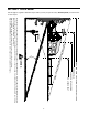
SECTION 11: PARTS LIST FOR MODEL 997 1 101 106 2 3 103 104 100 38 37 4 14 8 102 15 5 17 9 7 6 12 14 108 107 99 13 10 19 16 20 105 11 35 36 38 33 21 43 44 88 89 27 42 67 28 32 40 48 41 50 54 52 18 34 49 62 90 37 51 55 53 94 95 57 96 60 64 63 29 91 68 56 39 58 59 92 39 66 31 96 95 33 60 47 57 58 61 34 73 72 76 64 71 74 75 45 97 70 46 61 78 79 81 30 IMPORTANT: For a proper working machine, use Factory Approved Parts.
Model 997 Ref. No. 1. 2. 3. 4. 5. 6. 7. 8. 9. 10. 11. 12. 13. 14. 15. 16. 17. 18. 19. 20. 21. 27. 28. 29. 30. 31. 32. 33. 34. 35. 36. 37. 38. 39. 40. 41. 42. 43. 44. 45. 46. 47. 48. 49. 50. 51. 52. 53. 54. 55. 56. 57. 58. Part No.
Model 997 1 2 17 26 15 16 3 28 27 11 4 5 6 24 25 9 18 7 8 10 12 21 7 14 23 29 13 7 14 22 30 19 31 30 33 20 60 32 34 64 35 36 37 59 38 40 39 65 43 41 42 44 45 61 46 48 47 49 51 58 52 62 50 53 56 54 55 63 57 22
Model 997 Ref. No. 1. 2. 3. 4. 5. 6. 7. 8. 9. 10. 11. 12. 13. 14. 15. 16. 17. 18. 19. 20. 21. 22. 23. 24. 25. 26. 27. 28. 29. 30. 31. 32. Part No. 720-0223 732-0803A 738-0529 710-0751 736-0270 748-0318 736-0369 782-0566B 750-0515 741-0978 750-1056 710-0653 682-7528 741-0324A 682-7526 618-0263A 710-0604A 713-0453 638-0012 741-0522 732-0832 750-0151 710-1315 711-0835 750-0807 782-0568 710-1652 714-0474 712-3025 736-0425 756-0656 736-3084 Ref. No. Part Description Grip Spring Lever Shoulder Nut.825 x.
SAFETY AWARENESS WARNING: Whenever you see the symbols shown on the left, heed their instructions! Always follow safe operating and maintenance practices. FORWARD We wish to thank you for purchasing this Kawasaki engine. Please read this Owner's manual carefully before starting your new engine so that you will be thoroughly familiar with the proper operation of your engine's control, its features, capabilities and limitations. Also read the manual of the equipment to which this engine is attached.
READ THIS FIRST WARNING: Never allow children to operate the engine or equipment. Keep people and pets out of area where you are using the engine or equipment. Never wear loose, torn, or bulky clothing. It may catch on moving parts or controls, leading to the risk of accident. Never consume alcohol or drug before or while operating this engine. Do not run the engine in a closed area. Exhaust gas contains carbon monoxide, an odorless and deadly poison.
identified by the Periodic Maintenance Chart are necessary to ensure compliance with the applicable standards. A sealed-type crankcase emission control system is also used to eliminate blow-by gasses. The blow-by gasses are led to a breather chamber through the crankcase and from there to the air cleaner. As the owner of the engine, you have the responsibility to make sure that the recommended maintenance is carried out according to the instructions in this Owner's Manual at your own expense.
General Information Location of Safety Related Labels F Figure 3 A. Fuel Tank Cap Figure 1 B. Fuel Tank (capacity 2.0L [0.528US gal.]) C. Fuel Tube a. Warning b. Engine Maintenance D. Carburetor E. Priming Pump F. Air Cleaner G. Recoil starter H. Recoil Starter Grip I. Oil Drain Plugs (engine oil capacity 0.65L [0.69US gal.]) Figure 4 J. Oil Gauge / Filler Cap K. Spark Plug Cap / Spark Plug Engine Serial Number L.
Fuel And Oil Recommendations -20°C -10°C 0°C 10°C 20°C Fuel Use only clean, fresh, unleaded regular grade gasoline. 30°C 40°C SAE 40 SAE 30 SAE 10W-30/10W-40 Octane Rating The octane rating of a gasoline is a measure of its resistance to "knocking".Use a minimum of 87 octane of the antiknock index is recommended. The antiknock index is posted on service station pumps in the U.S.A. SAE 5W-20 Figure 5 NOTE: If "knocking or pinging" occurs, use a different brand of gasoline or higher octane rating.
• CAUTION: The engine is shipped without engine oil. • • DO NOT let the recoil starter grip snap back itself. This may cause damage to the recoil starter assembly. Hold the brake control lever (A) on the equipment against the handle (B) on the equipment. Pull the recoil starter grip (C) slowly until you feel compression, then pull fast and steady. Figure 7 Starting Band Pad System Upon releasing the brake control lever on the equipment, the cutting blade and the engine will stop automatically.
Adjustment B. Handle Engine Speed Adjustment NOTE: Do not tamper with the governor setting or the carburetor setting to increase the engine speed. Each carburetor is adjusted at the factory with either a cap or stop plate installed on the mixture screw. Any adjustments must be performed an authorized Kawasaki dealer.
• Refilling Fresh Oil Put the mower back to its operating position (on all four wheels). • Dipstick Remove dipstick and refill with new oil (See FUEL AND OIL RECOMMENDATIONS chapter). NOTE: If you followed the second method of draining oil, the dipstick is already removed from the engine. • Crank Case Check the oil level (See PREPARATION chapter), and secure dipstick to the filler plug. WARNING: Engine oil is toxic substance. Dispose of used oil properly.
A. Fasteners A. Slit in the air cleaner body B. Recoil Starter B. Projection on the air cleaner case C. Air Cleaner Case C. Fasteners D. Air Cleaner body CAUTION: After servicing the air cleaner, be sure all the removed parts are reinstalled properly in place. Failure to secure fastening of the air cleaner case with the air cleaner body may cause dirt or other foreign materials to enter the engine, while it is running, through the air cleaner, resulting in engine troubles or failures. E.
Storage Engine to be stored over 30 days should be completely drained of fuel (gasoline) to prevent gum deposits forming on essential carburetor parts and fuel system. WARNING: Gasoline is extremely flammable and can be explosive under certain conditions. Drain gasoline before storing the equipment for extended periods. Drain gasoline in a well-ventilated area away from any source of flame or sparks, including any appliances with a pilot light. Store gasoline in an approved container in safe location.
Troubleshooting Guide Symptom Engine won't start output is low Probable Cause Insufficient compression 1. Faulty piston, cylinder, piston ring, and head gasket Faulty valves Loose spark plug Loose cylinder head bolts 1. Tighten properly No fuel to 1. combustion chamber 2. 3. 4. No fuel in fuel tank Blocked rue tube Blocked air vent in fuel tank cap Faulty carburetor 1. Fill fuel tank 2. Clean 3. Clean 4. ‡ Spark plug fouled by fuel 1. Over-rich fuel/air mixture 2. 3. 4. 5.
Kawasaki Limited Warranty: California And Federal Emission Control Systems: Small Off-Road Engines The California Air Resources Board, the Environmental Protection Agency (EPA), and Kawasaki Motors Corp., U.S.A. (hereinafter "Kawasaki") are pleased to explain the Emission Control Systems Warranty on your Kawasaki small off-road engine. In California and other states, new small offroad engines must be designed, built and equipped to meet stringent anti-smog standards.
MANUFACTURER’S LIMITED WARRANTY FOR: The limited warranty set forth below is given by Cub Cadet LLC with respect to new merchandise purchased and used in the United States, its possessions and territories. “Cub Cadet” warrants this product against defects in material and workmanship for a period of two (2) years commencing on the date of original purchase and will, at its option, repair or replace, free of charge, any part found to be defective in materials or workmanship.