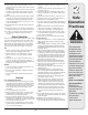
Safety • Assembly • Operation • Tips & Techniques • Maintenance • Troubleshooting • Parts Lists • Warranty OPERATOR’S MANUAL 21” Self-Propelled Mower — Model Series 990 IMPORTANT READ SAFETY RULES AND INSTRUCTIONS CAREFULLY BEFORE OPERATION Warning: This unit is equipped with an internal combustion engine and should not be used on or near any unimproved forest-covered, brushcovered or grass-covered land unless the engine’s exhaust system is equipped with a spark arrester meeting applicable local or state
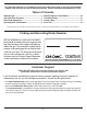
This Operator’s Manual is an important part of your new lawn mower. It will help you assemble, prepare, and maintain the unit for best performance. Please read and understand what it says. Table of Contents Slope Gauge........................................................ 3 Safe Operation Practices.................................... 4 Setup and Adjustment........................................ 6 Operating Your Lawn Mower............................... 8 Maintaining Your Lawn Mower.....................
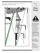
1 Use this page as a guide to determine slopes where you may not operate safely. Do not operate your lawn mower on such slopes. Slope Gauge 3IGHT AND HOLD THIS LEVEL WITH A VERTICAL TREE &O OR A FENCE POST OR A CORNER OF A BUILDING OT LD ALO NG D ESEN TED L I N E REPR LOPE TS A S WARNING Do not mow on inclines with a slope in excess of 15 degrees (a rise of approximately 2-1/2 feet every 10 feet). A riding mower could overturn and cause serious injury.
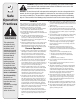
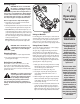
2 Safe Operation Practices WARNING This symbol points out important safety instructions which, if not followed, could endanger the personal safety and/or property of yourself and others. Read and follow all instructions in this manual before attempting to operate this machine. Failure to comply with these instructions may result in personal injury. When you see this symbol.
19. Shut the engine off and wait until the blade comes to a complete stop before removing the grass catcher or unclogging the chute. The cutting blade continues to rotate for a few seconds after the engine is shut off. Never place any part of the body in the blade area until you are sure the blade has stopped rotating. 20. Never operate mower without proper trail shield, discharge cover, grass catcher, blade control handle or other safety protective devices in place and working.
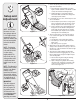
3 1. Remove any packing material which may be between upper and lower handles. Setup and Adjustment a. Pull up and back on upper handle as shown in Figure 3-1. Make certain the lower handle is seated securely into the handle mounting brackets. b. Tighten hand knobs securing upper handle to lower handle. Make sure that each carriage bolt is seated properly in the handle. 2. Locate hairpin clip in one hole on the weld pin on each side of lower handle. a. Remove hairpin clip from this hole.
3 c. Lift chute door on the grass bag adapter and slide grass bag onto the adapter. See Figure 3-5. 6. Follow steps below to install the side discharge chute: a. Remove mulching baffle or grass bag adapter from unit by disconnecting wing nuts. b. Attach side discharge chute to unit and secure with the three wing nuts. See Figure 3-6. Setup and Adjustment 2 7. The cutting height adjustment lever is located above the rear left wheel. See Figure 3-7A insert. a.
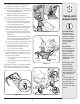
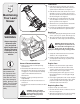
4 Know Your Lawn Mower Blade Control Electric Start Drive Control Operating Your Lawn Mower Shift Lever Recoil Starter Height Adjustment Lever WARNING The blade control mechanism is a safety device. Never attempt to bypass its operations. Use extreme care when handling gasoline. Gasoline is extremely flammable and the vapors are explosive. Never fuel the machine indoors or while the engine is hot or running. Extinguish cigarettes, cigars, pipes and other sources of ignition.
4 Starting Engine WARNING: Be sure no one other than the operator is standing near the lawn mower while starting engine or operating mower. Never run engine indoors or in enclosed, poorly ventilated areas. Engine exhaust contains carbon monoxide, an odorless and deadly gas. Keep hands, feet, hair and loose clothing away from any moving parts on engine and lawn mower. 3 2 3 1 1 Refer to engine manual for help with the engine. 1. Push primer once.
5 Lubrication 1. Lubricate pivot points on the blade control at least once a season with light oil. The blade control must operate freely in both directions. See Figure 5-1. 2. Lubricate wheels and casters at least once a season with light oil (or motor oil). If wheels are removed for any reason, lubricate the axle bolt and inner surface of the wheel with light oil. See Figure 5-1. Maintaining Your Lawn Mower 3.
5 Shift Lever Cable Periodic adjustment of the six speed shift cable may be necessary due to normal wear on the cable. Adjustment is needed if all six speeds do not work. The adjustable cable bracket is located on the left side of the mower beside the engine. See Figure 13. Start engine and place shift lever in the sixth speed position. Stop engine and disconnect spark plug wire and ground it against engine. 2 1 1. Loosen hex nut which secures the adjustable cable bracket. See Figure 5-3.
5 Belt Care 1. Disconnect the spark plug wire and ground it against the engine. 2. Drain the fuel tank or place a piece of plastic beneath the cap to prevent gasoline leakage. 3. Place shift lever in the first position and tip mower on its side (air cleaner side of engine up). Maintaining Your Lawn Mower 4. Move height adjustment lever to the highest position. 5. Remove blade, blade adapter, and related hardware as instructed in Blade Care above. Remove the three hex screws holding baffle to the deck.
12. Place the new belt over the transmission pulley. Start the belt in the pulley groove and rotate the pulley until the belt is seated in transmission pulley. Six Speed Cable Slot 13. Place the belt between the idler pulley and the belt keeper bracket. 14. Using pliers, rotate the belt keeper bracket so that it snaps into slot on the idler bracket. 5 Maintaining Your Lawn Mower 15. Tighten the idler pulley bolt and lock nut half a turn. 16.
5 Replacing Battery WARNING: Batteries contain sulfuric acid which may cause burns. Do not short circuit or mutilate batteries in any way. Do not put batteries in fire as these may burst or release toxic materials. Maintaining Your Lawn Mower 1. Loosen round handle knobs securing upper and lower handles and carefully fold the upper handle down toward the lower handle as shown in Figure 5-13. 2. Remove the two screws securing battery cover to battery housing and place them to the side. See Figure 5-13.
5 2. Insert the battery charger plug into a standard 120 volt household outlet. See Figure 5-15. Charge battery for 8 to 10 hours before initial use. Do not charge longer than 12 hours. The battery should only need to be charged upon initial setup and after any other extended periods of non-use. 3. After charging, disconnect charger plug from outlet first, then disconnect charger lead from battery.
6 Problem Engine fails to start Trouble Shooting Engine runs erratic For repairs beyond the minor adjustments listed here, contact an authorized service dealer. Engine overheats Occasional skips (hesitates) at high speed Idles poorly Excessive Vibration Mower will not mulch grass Cause 1. Blade control disengaged. 1. Engage blade control. 2. Spark plug wire disconnected. 2. Connect wire to spark plug. 3. Fuel tank empty or stale fuel. 3. Fill tank with clean, fresh gasoline. 4.
7 Off Season Storage and Safety Labels Safety Labels Found On Your Lawn Mower TO REDUCE THE RISK OF INJURY, DO NOT OPERATE UNLESS DISCHARGE COVER OR GRASS CATCHER IS IN ITS PROPER PLACE. IF DAMAGED, REPLACE IMMEDIATELY. WARNING DO NOT remove safety (or any) labels from mower for any reason. A V O I D S E R I O U S I N J U R Y O R D E AT H • K E E P H A N D S A N D F E E T A W AY F R O M ROTATING PARTS. • REMOVE OBJECTS THAT CAN BE THROWN BY THE BLADE IN ANY DIRECTION. WEAR SAFETY GLASSES.
Model Series 990 69 4 2 71 70 5 10 3 1 5 15 12 6 7 13 68 73 11 64 46 22 48 66 65 62 61 59 23 49 52 75 17 47 8 76 45 40 74 9 50 63 60 24 21 14 23 18 16 22 25 11 51 26 27 20 72 28 29 37 30 23 19 57 58 41 56 44 51 55 54 53 39 42 36 38 36 35 34 43 31 32 33 18 67
Ref. Part Number Description 647-04008 Blade Control 39 664-0180 Grass Catcher 2 731-0904A Upper Control Housing 40 747-0940A Support Rod w/ Rope Guide 3 731-0620A Drive Control 41 747-0939 Pivot Rod 4 731-0905A Lower Control Housing 42 747-0937 Grass Catcher Frame 5 710-1667A C Sunk Tap Screw, #10 x.
Model Series 990 12 6 14 13 20 21 47 43 24 22 45 44 25 29 27 2 37 23 34 1 35 32 59 28 53 42 36 31 55 7 8 11 39 38 23 10 48 23 56 18 46 52 49 9 14 16 17 30 5 13 56 18 41 6 48 26 30 40 23 19 3 12 4 50 57 20 51 19 33 33 54 58 55 15
Cotter Pin 29 682-7528 Chain Cover Assembly 2 710-1652 Screw 1/4-14 x .825 30 741-0324A Flge Bearing .506 ID x .590 Lg 3 736-0264 Flat Washer.330 ID x.630 OD 31 682-7526 Transmission Axle Assembly 4 714-0104 Cotter Pin 32 618-0263A Transmission Ass’y Complete 5 732-0306 Compression Spring 33 734-1857 Wheel 7 x 2 6 734-2010 Wheel, 9 x 2.
NOTES Use this page to make notes and write down important information.
NOTES Use this page to make notes and write down important information.
MANUFACTURER’S LIMITED WARRANTY FOR The limited warranty set forth below is given by Cub Cadet LLC with respect to new merchandise purchased and used in the United States, its possessions and territories. “Cub Cadet” warrants this product against defects in material and workmanship for a period of two (2) years commencing on the date of original purchase and will, at its option, repair or replace, free of charge, any part found to be defective in materials or workmanship.