Safe Operation Practices • Set-Up • Operation • Maintenance • Service • Troubleshooting • Warranty Operator’s Manual Two Stage Snow Thrower — Models 930 SWE & 933 SWE WARNING READ AND FOLLOW ALL SAFETY RULES AND INSTRUCTIONS IN THIS MANUAL BEFORE ATTEMPTING TO OPERATE THIS MACHINE. FAILURE TO COMPLY WITH THESE INSTRUCTIONS MAY RESULT IN PERSONAL INJURY. CUB CADET LLC, P.O. BOX 361131 CLEVELAND, OHIO 44136-0019 Printed In USA FORM NO.
1 To The Owner Thank You Thank you for purchasing a Snow Thrower manufactured by Cub Cadet LLC. It was carefully engineered to provide excellent performance when properly operated and maintained. Please read this entire manual prior to operating the equipment. It instructs you how to safely and easily set up, operate and maintain your machine. Please be sure that you, and any other persons who will operate the machine, carefully follow the recommended safety practices at all times.
Important Safe Operation Practices 2 WARNING! This symbol points out important safety instructions which, if not followed, could endanger the personal safety and/or property of yourself and others. Read and follow all instructions in this manual before attempting to operate this machine. Failure to comply with these instructions may result in personal injury. When you see this symbol.
Safe Handling of Gasoline 5. To avoid personal injury or property damage use extreme care in handling gasoline. Gasoline is extremely flammable and the vapors are explosive. Serious personal injury can occur when gasoline is spilled on yourself or your clothes which can ignite. Wash your skin and change clothes immediately. Never run an engine indoors or in a poorly ventilated area. Engine exhaust contains carbon monoxide, an odorless and deadly gas. 6.
Maintenance & Storage Do not modify engine 1. Never tamper with safety devices. Check their proper operation regularly. Refer to the maintenance and adjustment sections of this manual. 2. Before cleaning, repairing, or inspecting machine disengage all control levers and stop the engine. Wait until the auger/impeller come to a complete stop. Disconnect the spark plug wire and ground against the engine to prevent unintended starting. To avoid serious injury or death, do not modify engine in any way.
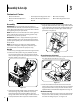
3 Assembly & Set-Up Contents of Carton • One Snow Thrower • Two Replacement Auger Shear Pins • One Chute Assembly • One Snow Thrower Operator’s Manual • One Tecumseh Engine Operator’s Manual Assembly IMPORTANT: Two replacement auger shear pins are included with this manual (or stowed in the plastic handle panel). Refer to the Maintenance section for more information regarding shear pin replacement.
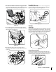
2. Place chute assembly onto chute base as shown in Figure 3-4. Make sure that the chute notches engage with the spiral end of chute directional control, and the two flange keepers are beneath the flange on the chute base. Headlight Harness If not already done, wrap the wires of the headlight wire harness around the lower right handle; then attach the wires to the engine as shown in Figure 3-7. A B Figure 3-7 Figure 3-4 3. Secure flange keeper removed earlier with lock nuts and screws.
Tire Pressure (Pneumatic Tires) The tires are over-inflated for shipping purposes. Check the tire pressure before operating the snow thrower. Refer to the tire side wall for tire manufacturer’s recommended psi and deflate (or inflate) the tires as necessary. NOTE: If the tire pressure is not equal in both tires, the unit may pull to one side or the other and the shave plate will not sit level on the ground. IMPORTANT: Under any circumstance do not exceed manufacturer’s recommended psi.
4. Allow the auger to remain engaged for approximately ten (10) seconds before releasing the auger control. Repeat this several times. 5. With the throttle control in the FAST (rabbit) position and the auger control in the disengaged “up” position, walk to the front of the machine. 6. Confirm that the auger has completely stopped rotating and shows NO signs of motion. If the auger shows ANY signs of rotating, immediately return to the operator’s position and shut off the engine.
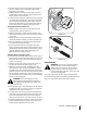
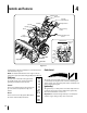
4 Controls and Features Drive Control Shift Lever Two-Way Chute Control™ Fuel Tank Auger Control Headlight Gas Cap Wheel Steering Control Oil Fill Chute Assembly Chute Directional Control Engine Controls Recoil Starter Handle Electric Starter Switch Primer Bulb Ignition Key Choke Control Clean-Out Tool Augers Throttle Control Skid Shoe Figure 4-1 Snow thrower controls and features are described below and illustrated in Fig. 4-1.
Throttle Control Auger Control The throttle control is located on the rear of the engine. It regulates the speed of the engine and will shut off the engine when moved into the STOP position. Primer Bulb Pressing the primer bulb forces fuel directly into the engine’s carburetor to aid in starting a “Cold” engine. NOTE: Do not use the primer bulb to restart a warm engine after a short shutdown. Oil Fill Engine oil level can be checked and oil added through the oil fill.
Two-Way Chute Control™ Wheel Steering Controls The two-way chute control is located on the left side of the dash panel and is used to control the distance of snow discharge from the chute. The left and right wheel steering controls are located on the underside of the handles. Squeeze the right control to turn right; squeeze the left control to turn left.
5 Operation Starting The Engine 1. Attach spark plug wire to spark plug. Make certain the metal loop on the end of the spark plug wire (inside the rubber boot) is fastened securely over the metal tip on the spark plug. 2. Make certain both the auger control and drive control are in the disengaged (released) position. 3. Move throttle control up to FAST position. Insert ignition key into slot. Make sure it snaps into place. Do not attempt to turn the key. 5.
To Engage Drive Operating Tips 1. NOTE: Allow the engine to warm up for a few minutes. With the throttle control in the Fast (rabbit) position, move shift lever into one of the six forward (F) positions or two reverse (R) positions. Select a speed appropriate for the snow conditions and a pace you’re comfortable with. NOTE: Use slower speeds in higher snow and/or until you are familiar with the snow thrower operation 2. Squeeze the drive control against the handle the snow thrower will move.
6 Maintenance & Adjustments Maintenance 3. Engine Refer to the Tecumseh Engine manual packed with your machine for all engine maintenance. Shave Plate and Skid Shoes The shave plate and skid shoes on the bottom of the snow thrower are subject to wear. They should be checked periodically and replaced when necessary. NOTE: The skid shoes on this machine have two wear edges. When one side wears out, they can be rotated 180° to use the other edge. To Remove skid shoes: 1.
Auger Shaft Adjustments At least once a season, one at a time, remove the shear pins from the auger shaft. Spray lubricant inside the hub of each auger spiral assembly and around the spacers on the auger shaft. See Figure 6-3. Shift Cable Grease fittings can also be found at each end of the auger shaft. Lubricate with a grease gun once a season. See Figure 6-3.
Drive Control 3. Refer to “Auger and Drive Control Cables” of the Assembly & SetUp - Section 3 for instructions to adjust the drive control. To further check the adjustment, proceed as follows: 4. 1. With the snow thrower tipped forward (be certain to drain gasoline or place plastic film under the gas cap if the snow thrower has already been operated), remove the frame cover underneath the snow thrower by removing the self-tapping screws. See Figure 6-6.
7 Service Belt Replacement Belt Removal Preparation Remove 1. Disconnect the chute crank assembly at the discharge chute end by removing the hairpin clip and the flat washer. Refer to Figure 7-1. Loosen Figure 7-3 Auger Belt Replacement Figure 7-1 2. Remove the plastic belt cover on the front of the engine by removing the three self-tapping screws. See Fig. 7-2. To remove and replace your snow thrower’s auger belt, proceed as follows: 1.
ensure the adapter does fall and get damaged when removing the pulley. 8. Place the new auger belt in the V-groove of the auger pulley and place the pulley w/belt inside the belt keepers. B Adapter Post Figure 7-5 4. From both sides of the frame assembly, use a 1/2" wrench to remove the three hex tap screws securing the transmission frame to the auger housing assembly. Refer to Figure 7-1. NOTE: Do not remove the lower hex flange lock nut on each side. 5.
To adjust, disconnect ferrule from brake bracket assembly. Thread ferrule in (towards idler) to increase tension on belt, or out to decrease belt tension. 3. Remove screws from the frame cover underneath the snow thrower (refer to Figure 7-9). Remove the right wheel from the axle. NOTE: The brake puck must always be firmly seated in the pulley groove when auger control is disengaged.
15. Place the belleville washer (rounded side toward head) onto the hex screw removed earlier, and insert the screw into the threaded hole of the hex shaft. 16. Gradually tighten the hex screw to fully seat the bearings in each side of the frame and to secure the hex shaft. 17. Position the frame cover on the bottom of the frame and secure with the self-tapping screws. Pivot the snow thrower down to its normal operating position. NOTE: If you placed plastic film under the gas cap, be certain to remove it.
8 Troubleshooting Problem Engine fails to start Remedy 1. Choke control not in ON position. 1. Move choke control to ON position. 2. Spark plug wire disconnected. 2. Connect wire to spark plug. 3. Fuel tank empty or stale fuel. 3. Fill tank with clean, fresh gasoline. 4. Engine not primed. 4. Prime engine as instructed in the Operation section. 5. Faulty spark plug. 5. Clean, adjust gap, or replace spark plug. 6. Safety key not inserted . 6. Insert key fully into the switch. 1.
9 Replacement Parts Component Description Part Number 30 Inch 33 Inch Extention Cord, 110V 929-0071 929-0071 Auger Drive Belt 954-04131 954-0222A Wheel Drive Belt 954-0367 954-0131 Friction Wheel Assembly 918-04178 918-04178 Friction Wheel w/Bonded Rubber 718-04034 718-04034 Lamp, 12V, (#1141) 925-1629 925-1629 Shear Pin, 1.
CUB CADET LLC MANUFACTURER’S LIMITED WARRANTY FOR snow throwers The limited warranty set forth below is given by Cub Cadet LLC with respect to new merchandise purchased and used in the United States, its possessions and territories, and by MTD Products Limited with respect to new merchandise purchased and used in Canada and/or its territories and possessions. c.