OPERATOR’S MANUAL SNOW THROWER MODELS 850 SWE 1130 SWE IMPORTANT: READ SAFETY RULES AND INSTRUCTIONS CAREFULLY Warning: This unit is equipped with an internal combustion engine and should not be used on or near any unimproved forestcovered, brush-covered or grass-covered land unless the engine’s exhaust system is equipped with a spark arrester meeting applicable local or state laws (if any). If a spark arrester is used, it should be maintained in effective working order by the operator.
TABLE OF CONTENTS Content Page Important Safe Operation Practices................................................................... 3 Assembling Your Snow Thrower ....................................................................... 5 Know Your Snow Thrower ................................................................................. 7 Operating Your Snow Thrower .......................................................................... 8 Making Adjustments .........................................
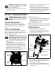
SECTION 1: IMPORTANT SAFE OPERATION PRACTICES WARNING: This symbol points out important safety instructions which, if not followed, could endanger the personal safety and/or property of yourself and others. Read and follow all instructions in this manual before attempting to operate this machine. Failure to comply with these instructions may result in personal injury. When you see this symbol - heed its warning.
3. 4. 5. 6. 7. 8. 9. 10. 11. 12. 13. 14. 15. 16. 17. 18. 19. The clutch levers must operate easily in both directions and automatically return to the disengaged position when released. Never operate with a missing or damaged discharge chute. Keep all safety devices in place and working. Never run an engine indoors or in a poorly ventilated area. Engine exhaust contains carbon monoxide, an odorless and deadly gas. Do not operate machine while under the influence of alcohol or drugs.
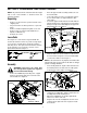
SECTION 2: ASSEMBLING YOUR SNOW THROWER NOTE: Any reference in this manual to the left or right side of the snow thrower is observed from the operator’s position. • • Unpacking • • • • • • Remove screws from the top sides and ends of the shipping crate. Set panel aside to avoid tire punctures or personal injury. Remove and discard plastic bag that covers unit. Remove any loose parts included with unit (i.e., Operator’s Manual, etc). Roll unit out of crate.
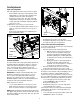
Final Adjustments Auger Control Adjustment Check the adjustment of the auger control as follows: • Push forward on the auger control until the small rubber bumper contacts the upper handle. There should be slack in the cable. See Figure 5 . • Release the auger control. The cable should be straight. Make certain you can depress the auger control against the left handle completely without using excess force.
• • Recheck the adjustment and repeat adjustment as necessary. Retighten the jam nut to secure the cable when correct adjustment is reached. NOTE: If you are uncertain that you have reached the correct adjustment, refer to Traction Control Adjustment in Adjustment Section.
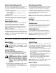
Electric Chute-Rotation Switch Wheel Steering Controls The electric chute-rotation switch is located on the left side of the snow thrower dash panel. See Figure 7. To change the direction in which discharged snow is thrown, proceed as follows: • Push the toggle switch to the left to rotate the chute counterclockwise. • Push the toggle switch to the right to rotate the chute clockwise.
Electric Starter: WARNING: The electric starter is equipped with a grounded three-wire power cord and plug and is designed to operate on 120 volt AC household current. It must be used with a properly grounded three-prong receptacle at all times to avoid the possibility of electric shock. Follow all instructions carefully prior to operating the electric starter.
• • • WARNING: The temperature of the muffler and the surrounding areas may exceed 150°F. Avoid these areas. • For the most efficient snow removal, remove snow immediately after it falls. Discharge the snow downwind whenever possible. Slightly overlap each previous path. Set the skid shoes 1/4" below the shave plate for normal usage. The skid shoes may be adjusted upward (to lower the shave plate) for hard-packed snow. Adjust downward (to raise the shave plate) when using on gravel or crushed rock.
• Reconnect the upper shift rod to the lower shift rod by reinserting the hairpin clip removed earlier and sliding the shift rod connector back down into place. Inside Hole In Axle IMPORTANT: Make certain to check for correct adjustment of the shift rod as instructed under Final Adjustments in the Assembly Section, before operating the snow thrower. Drive Wheels Click Pin In Outside Hole The wheels may be adjusted for two different methods of operation.
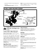
Auger Shaft At least once a season, remove the shear bolts on the auger shaft. Spray lubricant inside the shaft. Also lubricate the plastic auger bearings at least once a season and grease the fittings on the end of the auger shaft with a standard grease gun. See Figure 12. Lube Gear & Chute Base Vent Plug Grease Fitting Figure 11 Gear Case The gear case is equipped with a grease fitting on the left housing and should be lubricated with Shell Alvania grease EPR00, part number 737-0168 every 25 hours.
• Self-Tapping Screw • Unhook the idler spring from the hex bolt on the auger housing. See Figure 14. Back out the stop bolt until the support bracket rests on the auger pulley. NOTE: Loosening the six nuts that connect the frame to the auger housing may aid in belt removal. • • Belt Cover NOTE: If you placed plastic film under the gas cap, be certain to remove it before operating the snow thrower. Figure 13 • • Remove the six self-tapping screws from the frame cover underneath the snow thrower.
• • • Remove the six self-tapping screws from the frame cover underneath the snow thrower. Remove the click pin that secures the left wheel to the axle and slide the wheel from the axle. Remove the four screws securing the left drive cover to the frame. Remove the drive cover. See Figure 16.
SECTION 8: TROUBLE SHOOTING Problem Cause Remedy Engine fails to start 1. 2. 3. 4. 5. 6. 7. 8. Fuel tank empty, or stale fuel. Blocked fuel line. Choke not in ON position Faulty spark plug. Safety key not in ignition switch on engine. Spark plug wire disconnected. Primer button not being used properly. Fuel shut-off valve closed. 1. 2. 3. 4. 5. 6. 7. 8. Fill tank with fresh gasoline. Clean the fuel line. Move switch to ON position Clean, adjust gap or replace. Insert the key fully into the switch.
Notes 16
Models 826 SWE & 1130 SWE 4 17 11 9 16 13 8 15 1 14 5 10 6 18 7 3 12 2 Ref. No. Part No. 3 Part Description 1. 618-0123 RH Housing (Incl. Ref. 17, 18) 2. 618-0418 LH Housing w/Fitting (Incl. Ref. 17, 18) 3. 710-0642 Self Tapping Screw, 1/4-20 x .75 4. 711-0909 Spiral Axle, 26” (826 SWE) 711-1024 Spiral Axle, 30” (1130 SWE) 5. 714-0161 Hi-Pro Key, 3/16 x 5/8 6. 715-0143 Spring Spiral Pin, .25 x 1.25 7. 717-0528 Worm Gear, 20-tooth 8. 717-0526 Worm Shaft 9.
Models 826 SWE & 1130 SWE 68 27 57 58 57 58 55 65 72 70 80 53 73 72 27 69 82 71 27 68 83 74 63 59 67 69 27 58 56 54 64 81 66 77 60 66 78 58 76 31 45 79 62 11 75 61 9 15 13 29 51 40 46 37 13 47 5 8 2 5 14 17 24 20 22 10 14 21 3 50 11 9 40 18 16 41 12 4 25 26 1 31 11 43 9 42 27 15 19 35 39 14 35 7 36 48 38 10 49 For Reference Only 23 44 For Reference Only 44 28 30 32 18 52
Models 826 SWE & 1130 SWE Ref. No. Part No. Ref. No. Part Description Part No. Part Description 1. 684-0008A Shift Arm Assembly 44. 736-0242 Belleville Washer 2. 710-0262 Carriage Bolt 5/16-18 x 1.5” 45. 736-0506 Special Washer 3. 710-0449 Carriage Bolt 5/16-18 x 2.25” 46. 746-0896 Control Cable 4. 710-0788 TT Screw 1/4-20 x 1” 47. 746-0901 Control Cable 5. 710-0837 C-Sunk Screw #10-16x 0.625” 48. 750-1232 Spacer 7. 710-3008 Hex Screw 5/16-18 x .75” 49.
Models 826 SWE & 1130 SWE 3 1 2 4 5 11 10 9 15 18 14 7 12 6 8 13 16 22 23 27 34 21 10 28 25 23 9 13 26 38 35 30 19 18 32 31 33 16 36 41 37 17 39 40 40 24 39 42 29 20 20 22
Models 826 SWE & 1130 SWE Ref. No. Part No. Ref. No. Part Description Part No. Part Description 1. 712-0116 Lock Jam Nut 3/8-24 29. 741-0245 Hex Flange Bearing 2. 756-0178 Flat Idler 30. 784-5038B Skid Shoe 3. 784-5632A Auger Idler Arm 31. 736-0242 Bell Washer 4. 710-0459A Hex Cap Screw 3/8-24 x 1.50 32. 712-3010 Hex Nut 5/16-18 5. 738-0281 Shoulder Screw 33. 784-5579A Shave Plate (826 SWE) 6. 736-0167 Wave Washer 784-5575 Shave Plate (1130 SWE) 7.
Models 826 SWE & 1130 SWE 28 29 1 30 27 2 26 3 4 9 11 16 8 4 7 10 12 15 19 6 16 19 21 5 16 16 13 22 14 17 23 18 31 33 25 20 24 34 IMPORTANT: For a proper working machine, use Factory Approved Parts. V-BELTS are specially designed to engage and disengage safely.
Models 826 SWE & 1130 SWE Ref. No. Part No. Part Description 1. 710-1652 Hex Washer Screw 1/4-20 x .625 2. 731-1324 Belt Cover 3. 732-0710 Extension Spring 4. 710-0627 Hex Screw 5/16-24 x .75 5. 710-3005 Hex Cap Screw 3/8-16 x 1.25 6. 05896A Drive Clutch Idler Bracket 7. 748-0234 Shoulder Spacer 8. 756-0987 Pulley Half 9. 754-0346 V-Belt 10. 756-0986 Pulley Half 11. 736-0270 Bell Washer 12. 710-0230 Hex Cap Screw 1/4-28 x .50 13. 756-0313 Flat Idler 14.
Models 826 SWE & 1130 SWE 42 54 11 41 43 55 47 57 53 11 47 36 7 14 9 22 36 14 32 38 20 32 48 5 40 34 45 21 9 26 34 9 43 16 34 32 30 9 23 14 46 18 19 13 24 40 18 4 37 31 21 39 6 17 33 7 20 32 38 35 34 51 49 26 34 3 34 11 29 25 44 9 21 52 8 1 50 10 13 16 11 27 7 30 9 28 15 11 47 Drive Clutch Cable Routed Below Axle And Hooked Here 36 11 24 14 22 37 33
Models 826 SWE & 1130 SWE Ref. No. 1. Part No. 618-0043 Part Description Ref. No. Dogg Assembly: RH 30. Part No. 736-0169 Part Description Lock Washer 2. 618-0044 Dogg Assembly: LH 31. 784-5740 Drive Cover LH 3. 618-0303B Shift Assembly: Steerable Drive 32. 736-0351 Flat Washer 4. 656-0012A Friction Wheel Disc Assy. 33. 736-0626 Flat Washer 5. 684-0014B Shift Rod Assembly 34. 737-0170 Lubricant: 6 in 1 6. 684-0042B Bearing 35. 737-0318 Grease 7.
MANUFACTURER’S LIMITED WARRANTY FOR: TWO-YEAR RESIDENTIAL ONE-YEAR COMMERCIAL Proper maintenance of your Cub Cadet equipment is the owner’s responsibility. Follow the instructions in your operator’s manual for correct lubricants and maintenance schedule. Your Cub Cadet dealer carries a complete line of quality lubricants and filters for your equipment’s engine, transmission, chassis and attachments.