OPERATOR’S MANUAL SERIES 7000 COMPACT TRACTOR Model Numbers 7530 7532 IMPORTANT: READ SAFETY RULES AND INSTRUCTIONS CAREFULLY CUB CADET LLC P.O. BOX 361131 CLEVELAND, OHIO 44136-0019 [www.cubcadet.com] PRINTED IN U.S.A. FORM NO.
Off-Road Diesel Engine Emission Control SystemWarranty Statement Emission Related System Defect Warranty Manufacturer Statem Statement Mitsubishi Heavy Industries, ltd. (MHI) will give a warranty condition, required by the U.S. E nvironm ental Protection Agency(EPA) and the California Board(CA RB) to Original Equipment Manufacturers (OEMs) for small Air R esource off-road engines purchased in 1997 and later which ar e used in U.S.A.
Manufacturer’s Emission Control Warranty Coverage Manufacturer Applicable only to engines purchased in U.S.A. in 1997 and thereafter which are used in U.S.A. Emission control systems warranty coverage. The small off-road engines are warranted as to emission control parts defects for a period, which is prescribed by US EPA CFR Part 89, subject to provisions as set forth hereafter . If any covered part on your engine is defective, the part will be repaired by (OEMs).
Fuel injection system Fuel injection pump Fuel inj ectors Inlet system Intake manifold Exhaust system Exhaust manifold Turbocharger system Turbocharger (it equipped) Miscellaneous items used in above systems Cylinder Head Gasket Valve Stem Seal Length of Coverage MHI warrants to the initial owner and each subsequent purchaser that the warranted parts shall be free from defects in materials and workmanship which cause the failure of the warranted part(s) for a period, which is prescribed by US EP A CFR Part
which are not or iginal OEMs parts or because of abuse, neglect or i mpr oper maintenance as s et forth in the OEMs engi ne warranty policy . OEMs is not liable to cover failures of warranted parts caused by the use of add-on, non-original, or modified parts.
INTRODUCTION INTRODUCTION This instruction manual contains information on the operation, lubrication and maintenance of your tractor. The information contained is comprehensive and essential, and is designed to assist you, even if unexperienced, in utilizing your tractor. How well your tractor continues to give satisfactory performance depends greatly upon the manner in which it is operated.
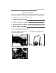
SERIAL NUMBERS SERIAL NUMBERS Write your machine Model Name and Serial Numbers of major components on the lines provided. If needed, give these numbers to your dealer when you need parts or information for your machine. 1. TRACTOR MODEL NAME 2. TRACTOR SERIAL NUMBER 3. ENGINE SERIAL NUMBER 4.
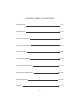
GENERAL TABLE OF CONTENTS Safety/Decals 1~13 Specifications 14~18 Instruments/Controls 19~35 Operating Instructions 36~54 Field Operation 55~64 Tires/Wheels/Ballast 65~75 Lubrication/Filters/Fluids 76~103 Maintenance/Adjustments 104~109 Electrical System 110~116 Storage 117~118 III
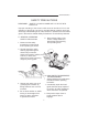
SAFETY/DECALS SAFETY PRECAUTIONS REMEMBER: “SAFETY” IS ONLY A WORD UNTIL IT IS PUT INTO PRACTICE Improper handling of the tractor could cause an accident. Prior to the operation of the tractor, be sure to read this Manual carefully and have a thorough understanding of all of the contents. In particular, the instructions given in this section entitled “Safety Precautions” must be strictly followed. A. GENERAL OPERATING SAFETY PRECAUTION 5.
SAFETY/DECALS 7. Hydraulic oil or fuel escaping under pressure can penetrate the skin, causing serious injury. Before disconnecting oil or fuel lines, be sure to relieve all pressure. Before restoring pressure after repair, be sure all connections are tight and all hydraulic components are in normal condition. If injured by leaked fluid, see a doctor immediately for proper treatment. 3. Cover the PTO shaft with a guard when not using. 4.
SAFETY/DECALS c) If diluted sulfuric acid has gotten on the skin of clothing: Wash away the diluted sulfuric acid completely with a lot of clean running water and neutralize with soap solution. Then rinse with water. 9. Before starting any work on electrical equipment or work that may cause you to touch the electrical parts accidentally, first disconnect the battery cables. Never remove the rubber cap cover at the positive terminal of the battery cable end.
SAFETY/DECALS C. OPERATION OF THE TRACTOR Before driving the tractor, follow these rules: C-1. Before starting and Driving the Tractor Operate the tractor only when seated properly in operator’s seat and keep a firm grip on the steering wheel at all times. Never attempt to perform any operation of the tractor from anywhere else, on or off the tractor. Always wear a “hard hat” when operating the tractor. To start traveling, lower the engine speed and release the clutch pedal slowly.
SAFETY/DECALS When starting the engine in an enclosed area or building, ensure proper ventilation by opening the doors and/or windows to prevent carbon monoxide inhalation. Mount the extension exhaust pipe on the tractor which has a cabin. Slow down when operating the tractor on rough ground. Never attempt to jump on or off a moving tractor. When starting the tractor, operating any attachment or engaging the PTO make sure that no one is in the way, especially children.
SAFETY/DECALS C-3. Traveling on Roads and Streets For traveling on roads and streets be sure to lock both brake pedals together before driving to prevent either brake from acting independently. C-4. Steering and Turning the Tractor Slow down your tractor and disengage the differential lock before going into a turn, being careful to prevent any attachments mounted on the front or rear from hitting anyone or anything C-5.
SAFETY/DECALS Avoid operating the tractor on an extreme slope that appears hazardous, when forced to operate on such slope, use extra care. Driving forward out of a ditch or mired condition or up a steep slope could cause tractor to tip over rearward. Back out of such situation if possible. If the situation does not permit you to back out, use the front wheel weight or the chassis weight for balancing the tractor lengthwise.
SAFETY/DECALS DECALS IMPORTANT: Install new decals if the old decals are destroyed, lost, painted over or can not be read. When parts are replaced that have decals, make sure you install a new decal with each new part. NOTE: New decals are available from your Dealer. WARNING EXPLO SI O N AN D I N JU RY C A N R E S U LT F R O M U S E O F S TA RT I N G A I D S W I T H HOT GLOW PLUGS. DO NOT INJECT GASOLINE O R E T H E R I N A I R I N TA K E .
SAFETY/DECALS WARNING R O TAT I N G M A C H I N E PA R T S S TAY C L E A R , K E E P S H I E L D S I N S TA L L E D TO H E L P P R O T E C T F R O M C L O T H I N G E N TA N G L E M E N T A N D I N J U RY. 321-3710 WARNING When improperly operated,this tractor can rollover or upset.Use of ROPS and seat belt minimize the possibility of injury or death if rollover or upset occurs.For low clearance use only,the ROPS can be lowered.
SAFETY/DECALS Tractor Roll Over ROPS is a special safety unit. After an accident the ROPS must be replaced so that you will get the same protection as a new ROPS. ROPS, the seat, the seat belts and all the mounting, accessories and wiring inside the operator’s protective area must be carefully checked after a tractor accident and all parts with damage should be replaced immediately. DO NOT TRY TO MAKE REPAIRS OR WELD ROPS. Safety Rules 1. Do not make modification to the ROPS.
SAFETY/DECALS ROLL OVER PROTECTIVE STRUCTURE (ROPS) Foldable ROPS Frame When improperly operated, this tractor can roll over or upset. Use of the ROPS and seat belt minimize the possibility of injury or death if rollover or upset occurs. For low clearance use only, the ROPS can be lowered. No protection is provided in this position and the seat belt should not be fastened. For all other uses, secure the ROPS in the upright position and the fasten the seat belt.
SAFETY/DECALS Low Clearance Positions For low clearance operation, such as operating in buildings, orchards or vineyards, the ROPS can be lowered and secured in the down position. No rollover protection is provided in the lowered positions and the seat belt should not be fastened. When the low clearance operation is completed, return the ROPS to the secured upright position for all other tractor uses and transport.
SAFETY/DECALS STEP 4 STEP 1 ( ROPS BAR NORMAL OPERATING POSITION HOLE ( POSITION PIN SLIT SLIT While holding the ROPS bar. CAREFULLY pull the position pins. STEP 5 ( STEP 2 ROPS BAR UPRIGHT POSITION ( POSITION PIN POSITION PIN Adjustment of Foldable ROPS. If you feel less friction when the ROPS is in the upright position, tighten the And then Rotate position pin to (90 ). nut untill you feel the right friction STEP 3 in the movement.
SPECIFICATIONS DIESEL ENGINE General Type Three Cylinders, Four Stroke Cycle, Valve in Cylinder Head, Cross Flow Porting Firing Order 1-3-2 Bore 84mm (3.307 inch) Stroke 90mm (3.543 inch) 3 Piston Displacement 1496cm (91.29 Cubic inch) Compression Radio 18.
SPECIFICATIONS Air Intake System Type Dry Type Air Cleaning System with 2nd Filter Cooling System Type Radiator Thermostat Pressure Cap Pressure System, Thermostat Controlled Bypass, Impeller Type Pump Corrugated and Wave Fin Type Start to Open at Approx.82 C (180 F) Fully Open at 95 C (203 F) 88.3kPa (12.
SPECIFICATIONS Clutch Type, Diameter Gear Drive Dry, Single Disc, Diaphragm Type, 215mm (8.46 Inch) Dry, Single Disc, Diaphragm Type, 215mm (8.
SPECIFICATIONS Hydraulic System Hydraulic Pump Type Front Mounted, Engine Driven, Pressure Loading Gear Type Capacity Pump for Three Point Hitch Maximum System Pressure 27.2 l/min (7.2GPM) at 2500 Engine RPM 12.3 l/min (3.3GPM) at 2500 Engine RPM 15200kPa (2204PSI) Auxiliary Connector Connector Size Front Hydraulic Block 9.
SPECIFICATIONS Overall length (To end of Lower link) 3080 mm (121 inch) Overall width (To end of tire) 7530 1360 mm (53.5 inch) 1365 mm 7532 Height (To top of ROPS) 7530 7532 (54 inch) 2110 mm (83 inch) 2140 mm (84.3 inch) Wheel base 7530 1710 mm (67 inch) Ground Clearance 7530 7532 370 mm (15 inch) 325 mm (12.8 inch) Turning Radius (with Brake Assistance) 7530 2300 mm (78.8 inch) 7532 2300 mm (78.
INSTRUMENTS/CONTROLS INSTRUMENTS AND INDICATORS 1. TACHOMETER AND HOURMETER [A] The tachometer shows the engine speed in revolutions per minute (RPM). A symbol on the face indicates the correct Power Takeoff (PTO) operating speed. The hour meter shows the hours and tenths of hours that the engine has operated at an average RPM. Yellow line [A] shows the 540 rpm of the Rear PTO speed. [B] Yellow line [B] shows the 2000 rpm of the MID PTO speed.
INSTRUMENTS/CONTROLS 2. ENGINE COOLANT TEMPERATURE GAUGE The gauge indicates the coolant temperature when the starter key switch is in ON position. If the engine overheats, the pointer moves right into H position area. In this case, run the engine at 1500 RPM without load until the pointer moves left out from H position area. If the pointer still stays in the H position area, stop the engine immediately and check for the cause. 3. FUEL GAUGE The meter shows how much fuel is in the tank.
INSTRUMENTS/CONTROLS 5. ENGINE GLOW PLUG INDICATOR This signal indicates the correct functioning of the glow plug circuit. When the glow plugs have reached the correct temperature for engine starting, the glow plug indicator lamp will be put out. 6. CHARGE INDICATOR The charge indicator indicates the battery is being discharged. If the lamp illuminates during operation, stop the engine and check for the cause. 7.
INSTRUMENTS/CONTROLS OPERATING CONTROLS Control Switches 2 4 3 1 5 1. STARTER KEY SWITCH The starter key switch can be removed with the switch in the OFF position. Four position switch as follows: position (OFF) Engine and all lamps except the turn signal and flasher lamps are turned off. First position clockwise from Position (HEAT) OFF. In this position (Engine not running) energizes the glow plugs. & The charge indicator, glow plug (ON) indicator and oil pressure indicator will illuminate.
INSTRUMENTS/CONTROLS 2. ENGINE SPEED CONTROL LEVER DECREASE Move the engine speed control lever to the rear to increase engine speed. Move the engine speed control lever forward to decrease engine speed. INCREASE ENGINE CONTROL LEVER 3. LAMP SWITCH LAMP SWITCH Three position switch as follows: ALL lamps are OFF. (Turn signal and flasher lamps can be turned on.) First position clockwise illuminates instrument panel lamp and rear red lamp.
INSTRUMENTS/CONTROLS 5. TURN SIGNAL SWITCH TURN SIGNAL SWITCH To indicate that you are going to turn the tractor to the RIGHT, move the turn signal switch to right . To indicate that you are going to turn the tractor to the LEFT, move the turn signal switch to left . Center position is OFF.
INSTRUMENTS/CONTROLS Control Levers and Pedals (Gear Drive) 3 1 (Hydrostatic Drive) 3 2 1. ACCELERATOR PEDAL (GEAR DRIVE ONLY) Use this pedal when operating the tractor on the road. Push the pedal down to increase engine speed. ACCELERATOR PEDAL 25 NOTE: The engine speed control lever must be set to give the slowest engine speed when the throttle pedal is used.
INSTRUMENTS/CONTROLS 2. SPEED RATIO CONTROL PEDAL (HYDROSTATIC DRIVE ONLY) The control pedal is spring loaded to the center or neutral position. Push down on the front of the pedal to increase forward speed. Push down on the rear of the pedal to increase reverse speed. 2 3. BRAKE PEDALS 3 4. BRAKE PEDAL LOCK 4 LOCK The pedals when locked together, provides braking to both rear wheels for stopping the tractor.
INSTRUMENTS/CONTROLS (GEAR Drive) (Hydrostatic Drive) ON BRAKE PEDAL 5 7 5. PARK BRAKE LEVER 5 PARK BRAKE 1. The park brake must be on to prevent movement of the tractor during stationary power takeoff work or when the tractor is parked. To engage the park brake, lock the brake pedals together, push down on the brake pedals and move the park brake lever downward. Push the brake pedal down to release the park brake. 2.
INSTRUMENTS/CONTROLS 6. SPEED LOCK LEVER (Hydrostatic Drive only) To keep a constant forward travel speed, move the lever fully upward, while holding the speed ratio control pedal at the desired 6 speed. It does not work in reverse. 7. CLUTCH PEDAL The clutch must be disengaged when starting the engine, stopping the tractor, storing the tractor and operating the following levers, gear shift lever, rear PTO lever, MID PTO lever If EQUIPED, MFD lever, shuttle lever. 7-1. SINGLE CLUTCH (7532) 1.
INSTRUMENTS/CONTROLS Control Levers (Gear Drive) 3 1 2 (Hydrostatic Drive) 3 2 1.GEAR SHIFT LEVER (Gear Drive only) The gear shift lever is used to shift the transmission gears into any of four speeds.
INSTRUMENTS/CONTROLS 2. RANGE SHIFT LEVER Move the range shift lever forward to place the transmission in H range. Move the lever rear ward to place the transmission in L range. Move the range shift lever forward to place the transmission in H range. Move the lever to the rearward to place the transmission in M or L range. The center position between M and L or H and M places the transmission in N. NOTE: Be sure the range shift lever is in N (Engine start) slot when starting the engine. 3-1.
INSTRUMENTS/CONTROLS 4. MID PTO CONTROL LEVER (IF EQUIPPED) Mo v e t h e le v e r f o rwa rd t o engage the Mid PTO. Move the lever rearward to disengage the Mid PTO. NOTE: Be sure the Mid PTO control lever is in OFF slot when starting the engine. NOTE: 1. The Rear and Mid PTO shaft can be operated at the same time. 2. When not using the Mid PTO shaft, cover the shaft with the Mid PTO cover. PTO switch is used to engage or disengage the Independent PTO clutch. Turn right to engage push to disengage.
INSTRUMENTS/CONTROLS (Gear Drive) 5 (Hydrostatic Drive) 5 5. HITCH CONTROL LEVER Use this lever to control the position of the hitch. Move the lever forward to lower the hitch to the required depth. Move the lever to the rear to raise the hitch to the required height.
INSTRUMENTS/CONTROLS (Gear Drive) 2 3 1 (Hydrostatic Drive) 3 2 1 1. DIFFERENTIAL LOCK PEDAL Push the pedal down to engage the differential lock. A spring inside the differential lock will push it out of engagement when pedal is released.
INSTRUMENTS/CONTROLS NOTE: When engaging the differential lock, push the clutch pedal down or bring speed ratio control pedal to Neutral, to stop the wheels that are rotating, then push the differential lock pedal. Do not engage the differential lock pedal while the wheels are rotating. Do not drive on roads, or at high speed anywhere, with the differential lock engaged. Difficult steering will occur, and can result in an accident.
INSTRUMENTS/CONTROLS OPERATORS SEAT The seat can be adjusted in 5 fore/aft position by the lever located under the RH side of the seat. The seat is adjustable fore and aft by moving a lever. SEAT ADJUSTING LEVER 1. Move the lever upward. 2. Move the seat rearward or forward to the required position then release the lever. 3. Push the seat rearward to make sure that the lock is engaged.
OPERATING INSTRUCTION BEFORE STARTING THE ENGINE Before starting your tractor for the first time and before each operating period after that, make these checks: 1. Make sure all persons who operate or do maintenance on the tractor understand that clean fuel is important. 2. Check all lubrication fittings for grease as given in the Lubrication Chart. 3. Check the oil level in the engine crankcase. Check the fluid level in the transmission. 4.
OPERATING INSTRUCTION RUN – IN PROCEDURE If run-in instructions for a new engine are not followed, you can cause damage to piston rings and cylinder walls. LOAD Never operate an engine immediately under full load. Allow the engine to warm up before operating it at full load. Run-in the engine carefully as shown in the table.
OPERATING INSTRUCTION NORMAL STARTING PROCEDURE IMPORTANT: It is very important that enough lubricant reaches the engine parts before operating the engine at rated speed. Operate controls only when seated in the operators seat. Engine can start with transmission in gear when neutral or safety start switch is by-passed: 1. Do not connect across terminals on starter. 2.
OPERATING INSTRUCTION STEP 5 STEP 3 OFF POSITION ENGINE SPEED CONTROL LEVER Put the REAR PTO and MID PTO control levers in the OFF (Engine start) position. Put the engine speed control lever at the middle position. STEP 6 STEP 4 Put the SHUTTLE lever in the N (Engine start) slot (Gear Drive). Turn the starter key switch to the heat & ON position. Wait until the glow plug indicator lamp is put out. (Approximately 1 to 3 seconds.
OPERATING INSTRUCTION STEP 7 STEP 8 START CLUTCH PEDAL Push the clutch pedal down. Turn key switch to start position until engine starts, but no more than 10 seconds, then release the key. Ru n e n g in e f o r t wo min u t e s a t 1500 RPM. STEP 9 When the engine starts, check the oil pressure indicators stay on, stop the engine and find out what is wrong. NOTE: If the oil pressure indicator stays on after the engine starts, stop the engine and check the oil level in the crankcase.
OPERATING INSTRUCTION 4. If the charge indicator comes on during operation, determine and correct the cause to avoid complete discharge of the battery and possible damage to other components of the electrical system. See your Dealer. 5. If the coolant temperature indicator comes on, remove the load and allow the engine to run at 1500 rpm until the indicator goes out. If the indicator does not go out within one minute, stop the engine and determine the cause.
OPERATING INSTRUCTION STOPPING THE ENGINE IMPORTANT: When stopping the engine after operating under heavy load, run the engine at 1500 RPM for a short period of time. This will allow the engine temperature to decrease gradually. STEP 1 STEP 3 STOP OFF Move the engine speed control lever to run engine at idle speed for three to five minutes to decrease the temperature of engine. Turn the key switch to OFF position. Remove the key.
OPERATING INSTRUCTION COLD TEMPERATURE OPERATION To start and operate your tractor during cold ambient temperatures, use these procedures: 1. BATTERY – Must have a full charge. 2. FUEL – Must be clean and with no water. See Fuel Specifications in this manual. 3. ENGINE OIL – Must have the correct viscosity for the ambient temperature range. 4. TRANSMISSION HYDRAULIC FLUID – Use Cub Cadet Hydraulic Transmission fluid. 5. COOLING SYSTEM – Must have ethylene glycol solution for protection. 6.
OPERATING INSTRUCTION IMPORTANT: During cold ambient temperatures, never run the engine at low idle speed for long periods of time. During cold ambient temperatures, if the engine will not heat to or keep the rated operating temperatures can cause damage to the engine can occur. Use the following procedures to warm the engine and transmission fluids, and to keep the correct operating temperatures. 1. WARMING THE ENGINE AND TRANSMISSION. A.
OPERATING INSTRUCTION TOWING When towing a tractor, follow these rules: 1. Never tow the tractor faster than a ground speed of 16 Km/h (10MPH). 2. Make sure all controls are in the neutral or OFF position. 3. Because of a possible loss of steering and brakes when the tractor engine is not running, use only a rigid towing bar and safety chains to pull the tractor.
OPERATING INSTRUCTION GEAR DRIVE TRANSMISSION The gear drive transmission has forward and a reverse gear section, a four-speed main shift gear section, and a three-speed range section. This arrangement gives 8 forward and 8 reverse speeds. Transmission Operation 1. Push the clutch pedal and stop the tractor. Move the gear shift lever to the gear needed. 2. Move the range shift lever to the position needed, H, L (The tractor must be stopped before the range lever is operated.) 3.
OPERATING INSTRUCTION HYDROSTATIC DRIVE TRANSMISSION The Hydrostatic drive transmission has a forward/reverse hydrostatic section and a three-speed range section. This arrangement gives three forward and three reverse speeds ranges. Transmission Operation 1. Push the clutch pedal fully and stop the tractor. Move the range shift lever to the position needed, H, M or L. 2. Release the clutch pedal slowly. 3. Operate the speed ratio control pedal to move the tractor.
OPERATING INSTRUCTION DIFFERENTIAL LOCK DIFFERENTIAL LOCK PEDAL DIFFERENTIAL LOCK PEDAL HYDROSTATIC DRIVE LEFT SIDE of the transmission GEAR DRIVE RIGHT SIDE of the transmission Your tractor has a differential lock that will make both rear wheels turn at the same speed. The differential lock prevents loss of power when one wheel does not have traction but the other wheel does have traction. It also provides a straight in line steering aid when opening up the field and to control implement overlap.
OPERATING INSTRUCTION POWER TAKEOFF (PTO) PTO driven machinery can cause serious injury or death, usually due to wrapped clothing. When required by the job to be in the drive shaft area, stay clear of rotating parts. Before working on the drive shaft, or servicing or clearing the driven machine, where applicable on this tractor, put the PTO clutch lever in the DISENGAGE position, the PTO lever in the NEUTRAL or OFF, and STOP the engine. Rear PTO (HST) The rear PTO is a 540 RPM with a 34.
OPERATING INSTRUCTION POWER TAKEOFF (PTO) Mid PTO (OPTION) The Mid PTO has a 25.4 mm (1 inch) diameter 15 spline output shaft. ENGAGE THE MID PTO AS FOLLOWS: 1. Push the clutch pedal fully. 2. Move the Mid PTO control lever to the ON position. 3. Release the clutch pedal slowly. CLUTCH PEDAL DISENGAGE THE MID PTO AS FOLLOWS: 1. Push the clutch pedal fully. 2. Move the Mid PTO control lever to the OFF (Engine Start) position.
OPERATING INSTRUCTION POWER TAKEOFF GUARDS All tractors have a safety guard for the Rear PTO shaft and safety cover for the Mid PTO shaft. REAR PTO GUARD Whenever a PTO driven machine is in operation, the PTO guard must be in place for most operations to prevent injury to the operator or bystanders.
OPERATING INSTRUCTION PTO OPERATING SAFETY For the safe operation of the PTO, follow these safe operating procedures. Three Point Hitch Connecting Implements 1. Connect the implement to the hitch. See THREE POINT HITCH SYSTEM in this manual. 2. Connect the implement driveline to the tractor. 3. Check the driveline for correct length and for free telescopic movement by lifting and lowering hitch system.
OPERATING INSTRUCTION DRAWBAR Your tractor is equipped with a drawbar. Use the drawbar for connecting all pull-behind implements. STORAGE PIN HOLE WITHOUT MID PTO DRAWBAR HITCH CONNECTING PIN HOLE IMPLEMENT CONNECTING PIN HOLE DRAWBAR OPERATING POSITION The drawbar must be in the storage position when using the three-point hitch.
OPERATING INSTRUCTION WARNING LAMPS FLASHER CONTROL BUTTON LAMP SWITCH TURN SIGNAL SWITCH The lamp switch has two positions. Turn the switch clockwise to illuminate the headlamp, rear red lamp, and instrument panel lamps. Push the flasher control button down to operate the amber warning lamps. When the turn signal switch is moved upward to make a right turn, the RH warning lamp will illuminate ON and OFF and the LH lamp will illuminate continuously.
FIELD OPERATION CONNECTING IMPLEMENT TO DRAWBAR The correct connection of the implement to the drawbar will prevent stress on both the tractor and the implement. To assure proper tractor operation and optimum implement performance, the implement must be connected to the drawbar correctly. 1. Connect pull-behind implements to the drawbar only. 2. Use a hardened steel hitch pin to connect the implement to the drawbar. Make sure the pin is held securely in place with a lock pin. 3.
FIELD OPERATION SAFETY CHAIN When towing equipment on a highway, use a safety chain as an auxiliary connection between the tractor and the towed equipment. The safety chain must have a rating greater than the gross load of the towed equipment. Connect the chain to the tractor drawbar support and the towed equipment as shown in the illustration. Check the adjustment of the safety chain by turning the tractor completely to the right and left. Adjust the chain as necessary.
FIELD OPERATION THREE POINT HITCH SYSTEM The three point hitch system gives position control and draft control (If equipped) of implements. This tractor is equipped with a category I hitch. The three-point hitch dimensions are shown in the following table. Cat I Implement Implement Identification Dimensions A – Gap in top of implement mast 44.5 mm (1-3/4 inch) B – Diameter of holes in top of Implement mast 19.1 mm (3/4 inch) C – Diameter of hitch pins 22.
FIELD OPERATION HITCH SYSTEM ADJUSTMENTS The upper and lower links must be adjusted correctly so the implement can work at the needed depth and the links are free to move up and down with the shape of the ground. UPPER LINK LIFT LINKS STABILIZERS LOWER LINKS Lift Links LOCK NUT TURN BUCKLE RH LIFT LINK LH LIFT LINK 1. Connect the lift links to the tractor and to the lower links. Make sure the lift links are installed on the proper Sides as shown below. 2.
FIELD OPERATION Upper Link The length A of the upper link can be adjusted from 470 to 750 mm (18.5 to 29.5 inches). UPPER LINK TURNBUCKLE Turn the turnbuckle clockwise to shorten the link or counterclockwise to lengthen the link. HOOK LOCK NUT IMPORTANT: After the upper link is correctly adjusted, make sure the lock nut is tightened against the turnbuckle.
FIELD OPERATION HITCH OPERATION Connecting Implement to Hitch To connect an implement to the hitch, use the following procedure: NOTE: Be sure the tractor and implement are on level ground. 1. Put the drawbar in the storage position. 2. Slowly move the tractor backwards to the implement. 3. When the hitch points on the tractor and implement are in the correct position, stop the tractor. 4. Apply the park brake and stop the engine. 5. Connect the implement to the Upper and Lower Links. 6.
FIELD OPERATION Hitch Control Lever HITCH CONTROL LEVER RAISE STOP LOWER STOP The hitch control lever is used to raise or lower the implement mounted to the three point hitch. To raise the hitch, move the lever to the rear. To lower the hitch, move the lever forward. Adjustable stops are provided for use whenever it is desirable to return the hitch control lever to the same operating position.
FIELD OPERATION Hitch Lowering Speed Adjustment To adjust the hitch lowering speed, use the following procedure: 1. Move the hitch control lever forward to lower the implements. 2. Turn the hydraulic flow control knob to adjust the lowering speed. Turn the knob counter clockwise to increase the lowering speed. Turn the knob clockwise to decrease the speed or lock the hitch. 3. After adjusting the speed, raise the hitch and then lower it to check the speed.
FIELD OPERATION HYDRAULIC BLOCK A hydraulic block is located on the right side of the tractor. This block can provide an external hydraulic circuit for loader use or other applications. See your dealer. HYDRAULIC BLOCK IMPORTANT: Never park a tractor with an implement in the raised position. Moving the control lever forward will lower the implement even though the engine is not running.
FIELD OPERATION Adding Fluid after Connecting Cylinders and Hoses Operate the engine at a moderate idle speed. Set the stroke stop at the yoke end of the cylinder rod to provide maximum stroke. Then operate the cylinder in both directions about ten times, by moving the control lever up and down. This will fill the cylinder and hoses with fluid and remove the air from the system. Fill the cylinder completely, stop the engine and check the fluid level with the transmission dipstick.
TIRES/WHEELS/SPACING/BALLAST TIRE AND RIM EQUIPMENT Tire Inflation Specifications For normal tractor operation use the inflation pressure shown in the tire and wheel chart. The inflation pressure are based on cold inflation pressure recommendations by Tire and Rim Association Inc. For maximum tractor performance always adjust the tire pressure, within the minimum/maximum range to conform with the actual load on the tires. Under normal conditions use the minimum pressure rating for general drawbar work.
TIRES/WHEELS/SPACING/BALLAST A tire can explode during inflation and cause serious injury or death. Never increase air pressure beyond 35 PSI to seat the bead on the rim. Replace a tire if it has a direct. Replace a wheel rim which has cracks, wear or severe rust. Make sure that all the air is removed from a tire before removing the tire from the rim. Never use force on an inflated or partially inflated tire. Make sure the tire is correctly seated before inflating.
TIRES/WHEELS/SPACING/BALLAST Check Air Pressure Tire Pressure Check Interval Every 50 hours of operation or weekly. Check the condition of the tires and rims for wear or damage. Keep the tires inflated to the recommended pressures. See Tire and Wheel Specifications in this manual for recommended inflation pressures for each tire size. For tires equipped with liquid ballast, check the air pressure as follows: 1. Use an air-water gauge.
TIRES/WHEELS/SPACING/BALLAST WHEEL MOUNTING TORQUES Front Wheel Disc to Axle Hub Bolts 147 to 166 Nm (87 to 98 lb ft) Rear Wheel Disc to Axle Hub Bolts 147 to 166 Nm (87 to 98 lb ft) Rear Wheel Rim to Wheel Disc Nuts 152 to 172 Nm (112 to 127 lb ft) IMPORTANT: Check the wheel bolts and nuts after the first 10 hours of operation and again after every 100 hours of operation. Also do this procedure any time the wheel or rim is removed.
TIRES/WHEELS/SPACING/BALLAST FRONT WHEEL ADJUSTMENT 109 to 123 LB FT (147 to 166 Nm) The front wheels are tightened with six bolts for MFD to the axle hubs. Torques for wheel bolts and tie rod end nuts as follows: BOLTS AND NUTS POSITIONS TORQUE Front wheel disc to axle hub bolts 147 to 166 Nm (109 to 123 LB FT) Tie rod end nuts 59 to 88 Nm (43 to 65 LB FT) Check the bolts to keep them tight at the intervals recommended in the Service Chart in this manual.
TIRES/WHEELS/SPACING/BALLAST Toe-in Adjustment TO CHECK THE TOE-IN, USE THE FOLLOWING PROCEDURE: 1. Put the tractor on level ground and the wheels in the straight-ahead position. 2. Place chalk marks at points A on the centerlines of both front tires at the same height as the centerline of the hubcap. 3. Measure the distance (L1) between the chalk marks at points A. 4. Move the tractor forward a distance equal to one-half revolution of the front wheels. 5. The chalk marks will now be at points B.
TIRES/WHEELS/SPACING/BALLAST TO ADJUST THE TOE-IN, USE THE FOLLOWING PROCEDURE: Adjust the rods to be equal the dimensions A on both side. 1. Loosen the lock nut at the rod end. 2. Turn the rod to shorten or lengthen the tie rod. 3. Look the lock nuts.
TIRES/WHEELS/SPACING/BALLAST Tractor Equipped with Adjustable Wheels If you need to change the position of the discs and rims of the wheels, use the following procedure: 1. Put blocks at the front wheels, lift the rear of the tractor and put blocks under the tractor. 2. Remove six wheel mounting bolts at each wheel to remove rear wheels from rear axle. 3. Remove wheel disc from the wheel rim at each wheel. 4.
TIRES/WHEELS/SPACING/BALLAST TIRE SIZE COMBINATIONS-MFD Your MFD Tractor must use front and rear tire combinations that are correctly matched. The use of recommended tire combinations will give maximum tractor performance, extended tire and reduced wear on drive train components. IMPORTANT: The tire size combinations shown below are specified to provide matched ground speeds of the front and rear tires.
TIRES/WHEELS/SPACING/BALLAST TRACTOR BALLAST Ballast for your tractor includes front-end weights, rear wheel weights and liquid ballast in the rear tires. Front-end weights improve the steering characteristic when heavy hitch loads cause a movement of tractor weight from the front to the rear wheels. Rear wheel weights and adding liquid to the rear tires increase traction by putting weight on the driving wheels. IMPORTANT: The Maximum operating weight of tractor should not exceed the following values.
TIRES/WHEELS/SPACING/BALLAST NOTE: When you have too much ballast installed on the tractor, you will see the clear shape of the tire tread in the ground which is an indication of no slippage. With too little ballast, the tire tread marks will not show because of the tire slippage.
LUBRICATION/FILTERS/FLUIDS HOOD To do maintenance work on the engine lubrication system, cooling system, fuel system and air induction system, you must life the tractor hood. STEP 1 Pull the Lever release the hood. STEP 2 BONNET PROP ROD Lift the hood, and insert the Support Rod into hole. Remove both side covers.
LUBRICATION/FILTERS/FLUIDS Lubrication Table Application Engine Kind of oil Engine Oil API Classification CC CD Ambient Grade (SEA No.) Temperature Single Multi 5W 5W-20 -10 C (14 F) -20 -0 C (-4-32 F) -10-10 C (14-50 F) 0-20 C (32-68 F) 10-30 C (50-86 F) 30 C (86 F) 10W* 20W 20 Use High Grade Diesel Oil Cub Cadet Engine Oil 737-3030A 10W30 Use high Grade 30* 40 Description 20W-40 Use Cab Cadet Hydraulic Transmission Fluid Cub Cadet Size Part No.
LUBRICATION/FILTERS/FLUIDS SERVICE HOUR INTERVAL Service your tractor at the intervals and locations given on the Lubrication and Service Chart. When you service your tractor, use only high quality lubricants. Engine Hour meter [A] [B] The engine hour meter shows the amount of actual hours of the tractor has operated at an average RPM. The first number to the right displays tenths of an hour and is a black number on a white surface. The remaining numbers are white on black.
LUBRICATION/FILTERS/FRUIDS Service After First 50 Hours 1. Engine Oil Drain all the oil from the crankcase while the engine is warm and refill with new oil to the upper Notch (full) on the engine oil dipstick. See Engine Oil Change in this manual. 2. Engine Oil Filter Replace the engine oil filter. See Engine Oil Filter in this manual. 3. Transmission & Hydraulic System. (1) Transmission Oil Check the level of the transmission oil. Add the specified fluid as needed to maintain proper level.
LUBRICATION/FILTERS/FLUIDS SYSTEM CAPACITIES SYSTEM U.S. METRIC IMPERIAL MEASURE MEASURE MEASURE Engine Oil Filter change 4.7 QTS 4.5 Litres 4.0 QTS with filter change 5.3 QTS 5.0 Litres 4.4 QTS 7.1 Gallons 27 Litres 5.9 Gallons Engine and radiator 5.8 QTS 5.5 Litres 4.9 QTS coolant bottle 0.4 QTS 0.4 Litres 0.4 QTS gear drive 31.7 QTS 30 Litres 26.4 QTS hydrostatic drive 32.7 QTS 31 Litres 27.3 QTS 4.2 QTS 4.0 Litres 3.
LUBRICATION/FILTERS/FLUIDS SERVICE POINT Engine Oil Level Front Axle Tie Rod Front Axle Pivot Pin Popwer Steering Cyllinder End Brake Pedal Boss Transmission Oil Level Radiator Coolant Level Fuel Fillter Cup Air Cleaner Fan Belt Tension Grill and Radiator Area Tire Pressure Fuel Tank Water Drain Plug Engine Oil Wheel Retaining Bolts and Nuts Engine Oil Filter Transmission Oil Hydroustaic Filter (Hydrostatic Drive) Hydraulic Filter MFD-Front Axle Lubricant Clutch Pedal Brake Pedal Air Induction Systems Eng
82
83
LUBRICATION/FILTERS/FRUIDS ENGINE LUBRICATION Service Specifications Oil Level Check Interval Daily Oil Change Interval Every 100 hours (See NOTE) Oil Type See Lubrication Table in this manual. Oil Capacity Without Filter Change 4.5 Liters (4.7 QTS) With Filter Change 5.0 Liters (5.3 QTS) NOTE: Change the engine oil after the first 50 hours of operation and then use the regular change interval.
LUBRICATION/FILTERS/FRUIDS Engine Oil Change To change the engine oil, put the tractor on level ground and stop the engine. Change the engine oil as follows: NOTE: For best results change the oil while the engine is still warm. OIL FILL CAP DRAIN PLUG 1. Remove the oil pan drain plug and drain the oil from the engine. 2. See Engine Oil Filter in this manual, if the filter is to be changed. 3. Install the drain plug in the oil pan. Tighten the plug to a torque of 50 to 60 Nm (36 to 43 lb ft). 4.
LUBRICATION/FILTERS/FRUIDS Engine Oil Filter Change Interval Every 200 hours (See NOTE) NOTE: Change the engine oil filter after the first 50 hours of operation and then use the regular change interval. IMPORTANT: Change the oil filter at the recommended time interval. Your Dealer has approved genuine filters. Do not use other type filters. Change the engine oil filter as follows: REMOVE INSTALL 1. Drain the oil from the engine. See Engine Oil Change in this manual. 2.
LUBRICATION/FILTERS/FRUIDS COOLING SYSTEM Service Specifications Coolant Change Interval Every 1000 hours or once each year whichever occurs first. Capacity of System Engine and Radiator Coolant bottle Thermostat Radiator Cap Pressure 5.5 Liters (5.8 QTS) 0.4 Liters (0.4 QTS) 82 C to 95 C (180 C to 203 F) 88.2 kPa (12.8 PSI) Daily before starting the engine, check the coolant level the coolant reserve bottle. The coolant level should be between the "FULL" and "LOW" lines when the engine is cool.
LUBRICATION/FILTERS/FRUIDS Coolant Solutions Your tractor cooling system is equipped with an ethylene glycol coolant solution that has a high boiling point. IMPORTANT: Change the coolant solution at the change interval recommended in this manual (See Lubrication and service Chart). The heat generated by the diesel engine causes a natural change in the inhibitors in the coolant, which results in loss of corrosion protection.
LUBRICATION/FILTERS/FRUIDS Cleaning The Cooling System IMPORTANT: NEVER PUT COOLANT IN A HOT ENGINE: THE ENGINE BLOCK OR CYLINDER HEADS CAN GET CRACKS BECAUSE OF THE DIFFERENCE IN TEMPERATURE BETWEEN THE METAL AND THE COOLANT. CAP COOLANT RECOVERY RESERVOIR FULL LOW Clean the cooling system each time the coolant is changed. See the Lubrication and Service Chart in this manual for recommended change intervals. Clean the system as follows: 1. Remove the hose from to drain the coolant.
LUBRICATION/FILTERS/FRUIDS FUEL SYSTEM Service Specifications Fuel Filter Cup Service Interval Fuel Filter Element Change Every 10 Hours Replace when loss of power or misfiring occurs This type filter cannot be cleaned. Change the filter when the engine is misfiring or a loss of power is evident. It is necessary to remove the air from the system after each replacement.
LUBRICATION/FILTERS/FRUIDS Diesel Fuel Specifications Use a good grade of Number Two Diesel Fuel in your Diesel Engine. Do not use other types or fuel. The use of other fuels will result in loss of engine power and high fuel consumption. NOTE: When the temperature is very cold, the use of a mixture of Number one and number Two Diesel Fuel is permitted for a short period of time. See your fuel Dealer for winter fuel requirements in your area. Specifications For Acceptable Number Two Diesel Fuel A.P.I.
LUBRICATION/FILTERS/FRUIDS Fuel Filter Element Replacement To replace the filter element, use following procedure: STEP 4 STEP 1 FUEL SHUT-OFF VALVE CLOSE FILTER ELEMENT Close the fuel shut-off valve. STEP 2 Install new filter element. Assemble filter cup and retaining nut to filter body. NOTE: Be sure O-ring is in place on the filter body and filter cup. STEP 5 Clean the outside of the filter body and cup to prevent dirt or foreign materials from entering the system.
LUBRICATION/FILTERS/FRUIDS Fuel System Air Removal AIR MUST BE REMOVED FROM THE FUEL SYSTEM. AIR CAN ENTER THE FUEL SYSTEM WHEN: 1. 2. 3. 4. 5. An engine stopped from lack of fuel. The fuel filter has been replaced or the filter cup has been cleaned. Any connections between the injection pump and fuel tank have been loosened or disconnected for any reason. The tractor has not been operated of time. The fuel pump has not operated correctly.
LUBRICATION/FILTERS/FRUIDS Fuel Injection Pump and Nozzle Check NOZZLE INJECTION PUMP The fuel injection pump and nozzles are precision units and must be serviced only by your dealer. The injection pump is correctly set and sealed at the factory and should not require an adjustment. Whenever adjustment or repairs are necessary, see your dealer. Do not tamper with any of the pump units. Hydraulic oil or diesel fuel leaking under pressure can penetrate the skin and cause injection or other injury.
LUBRICATION/FILTERS/FRUIDS AIR INDUCTION SYSTEM The air induction system components require service at different intervals according to local operating conditions. Service Specifications Dump Valve Filter Element Clean Element Replace Element System Inspection Clean daily or every 10 hours When necessary After 10 cleanings or yearly Every 200 hours or yearly whichever occurs first Your tractor is equipped with a dry-type air cleaner with a replaceable element.
LUBRICATION/FILTERS/FRUIDS Air Filter Element Removal Avoid over servicing the air filter element. The filter element should be removed for cleaning only when restriction causes a power loss. STEP 4 STEP 1 ELEMENT Stop the engine OUTER STEP 2 INNER After replacing the new or cleaned element, install and tighten the wing bolt. Lift the hood and connect the hood support rod. NOTE: Never attempt to remove the element from the air cleaner while the engine is running.
LUBRICATION/FILTERS/FRUIDS Element Cleaning Use clean, dry compressed air up and down the pleats on the clean side (inside) of the element. Continue this until the element is clean. NOTE: 1. The paper element must be handled with care. Do not hit the element against a hard surface. 2. Air pressure at the nozzle must not exceed 689 kPa (100 PSI). 3.
LUBRICATION/FILTERS/FRUIDS TRANSMISSION & HYDRAULIC LUBRICATION Service Specifications Oil Level Check Interval Oil Change Interval Oil Capacity - Gear Drive Hydrostatic Drive Oil Type - Gear Drive Hydrostatic Drive Hydraulic System Check Daily Every 200 hours. 28 Liters (29.6 Quarts). 31 Liters (32.7 Quarts). STOU OIL or TOU OIL STOU OIL Yearly inspect for leaks, cracks and abrasion. Tighten fittings or replace as needed.
LUBRICATION/FILTERS/FRUIDS Transmission Oil Change Oil Change Interval Every 200 hours To change the transmission oil, use the following procedure: 1. 2. Put the tractor on level ground, apply the park brake and stop the engine. Move the range shift lever to L position. TRANSMISSION DRAIN PLUG Remove the drain plugs from the transmission case. (5 ) NOTE: For best results, drain the oil when the oil is warm. 3. Replace the hydraulic filter. See Hydraulic Filter in this manual. 4.
LUBRICATION/FILTERS/FRUIDS Hydraulic Filter (Gear & Hydrostatic Drive) Change Interval Every 200 hours (See NOTE) NOTE: Replace the hydraulic filter after the first 50 hours of operation and every 200 hours of operation thereafter. Your Dealer has approved genuine filters. Do not use other type filters. HYDRAULIC FILTER CHANGE THE HYDRAULIC FILTER AS FOLLOWS: 1. Put the tractor on level ground, move the range shift lever to the L position and apply the park brake. 2.
LUBRICATION/FILTERS/FRUIDS Hydrostatic System Filter (Hydrostatic Drive) Filter Change Interval Every 200 hours (See NOTE) NOTE: Change the filter after the first 50 hours of operation and every 200 hours of operation thereafter. Replace the filter more frequently when operating under unusual dirt and dust conditions. Your Dealer has approved genuine filters. Do not use other type filters.
LUBRICATION/FILTERS/FRUIDS FRONT AXLE LUBRICATION (MFD) Service Specifications Oil Change Interval Oil Capacity Oil Type Every 200 hours (See NOTE) 4.0 Liters (4.2 Quarts) SAE 85W-140 Gear Lubricant NOTE: Change the oil after the first 50 hours of operation and then every 200 hours of operation. DRAIN PLUG Front Axle Oil Level To check the front axle oil level, put the tractor on level ground. Remove the oil level plugs located on the rear of the both gear cases.
LUBRICATION/FILTERS/FRUIDS Front Axle Oil Change 1. To change the front axle oil, put the tractor on level ground. Put the range lever in L, engage the park brake and stop the engine. DIFFERENTIAL DRAIN PLUG FILL HOLE 2. Remove the fill cap located on the axle housing, the differential drain plug located in the bottom of the housing and the gear case drain plugs located on the bottom of both side gear cases to drain the oil. NOTE: For best results, drain the oil when the oil is warm. DRAIN PLUG 3.
MAINTENANCE/ADJUSTMENTS COOLING SYSTEM Grille Screens and Radiator Area Grille Screens and Radiator Area Service Interval Every 50 hours or more frequently if required. To clean the radiator screen, put the tractor on level ground, apply the park brake and stop the engine. STEP 1 STEP 2 RADIATOR SCREEN Lift and Lock the hood. Lift the radiator screen. STEP3 Clean the radiator screen and the surrounding area. STEP4 Install the radiator screen. Lower the hood.
MAINTENANCE/ADJUSTMENTS Fan Belt Adjustment Fan Belt Tension Check Interval Daily or after 10 Hours NOTE: Adjust the belt tension after the first 50 hours of operation and replace when necessary. Measure the fan belt for correct tension. Check to see if the belt deflection is about 13mm (0.5 inch) when pushing the belt with 10 kg (22 lb) load at point 1 . ADJUSTING BOLT PIVOT NUT Rotating fan and belts. Contact can injure. Keep clear.
MAINTENANCE/ADJUSTMENTS Fan Belt Replacement To replace the fan belt, use following procedure: STEP 1 BONNET STEP 3 PIVOT NUT Open Bonnet. STEP 2 Loosen the alternator pivot nut and push the alternator toward the engine to remove the belt. ADJUSTING BOLT STEP 4 Loosen the alternator-adjusting bolt. Install new fan belt and adjust the belt tension. See Fan Belt Adjustment in this manual for instructions.
MAINTENANCE/ADJUSTMENTS CLUTCH PEDAL ADJUSTMENT Service Specifications Clutch Pedal Check and Adjustment Interval Free Pedal Movement Every 200 hours of operation or yearly 20-30mm (0.8 - 1.2 inch) Free Movement Adjustment Clutch pedal free movement is very important and must be checked at the recommended intervals. If there is no free movement, the clutch disc will wear quickly. If there is too much free movement, the clutch will not disengage correctly and the transmission will be difficult to shift.
MAINTENANCE/ADJUSTMENTS BRAKE PEDAL ADJUSTMENT Service Specifications Brake Pedal Check and Adjustment Interval Free Pedal Movement Specification Every 200 hours or yearly 35mm (1.4inch) Brake pedal free play is very important and must be checked at the recommended intervals. If there is no free movement, the brake shoes will wear quickly. If there is too much free movement, accidents may occur. If there is not the same free movement between LH pedal and RH pedal, it may cause serious accidents.
MAINTENANCE/ADJUSTMENTS RAISE STOP SETTING POSITION If raise stop setting position is incorrect, the hydraulic pump might be damaged. Therefore carefully adjust as below. HITCH CONTROL LEVER RAISE STOP 1. Disconnect an implement from the hitch. (See Disconnecting Implement from Hitch in this manual.) 2. Disconnect LH and RH lifts rods from the lift arms. 3. Start the engine. Rotating fan and belts. Contact can injure. Keep clear. 4.
ELECTRICAL SYSTEM SPECIFICATIONS Electrical System Type of System Battery 12 Volt, Negative Ground 12 Volt, 500 CCA Group 22F, Top Stud Terminals Alternator 7530/7532 12 Volt, 50 Ampere Output Voltage Regulator IC Built in Alternator Starter Motor 7530/7532 12 Volt, 1.7 kw with Solenoid Switch Head Lamp 25 Watt Flasher Lamp 27 Watt Rear Red Lamp 10 Watt Rear Working Lamp (If Equipped) 23 Watt Panel Lamp 3 Watt Turn Indication Lamp 1.4 Watt Indicator Lamp 1.
ELECTRICAL SYSTEM GENERAL SERVICE INFORMATION Alternator Charging System Follow these general rules to prevent damage to the electrical system: 1. Before working on the electrical system, disconnect the battery cables. 2. Do not make a reverse battery connection. 3. When you use an auxiliary battery for starting, connect positive-to-positive and negative on the auxiliary battery to the tractor side rail as a ground. 4.
ELECTRICAL SYSTEM Fuses Cartridge type fuses are used for headlamps, rear red lamp, instrument lamps, turn signal and flasher lamps, and rear work lamp (if equipped). The fuses are located in the fuse block, R.H. rear of engine room. If a short circuit occurs, the fuse will burn out and break the circuit, preventing damage to the electrical system. Rotating fan and nd d belts. belt Contact C can injure. Keep clear.
ELECTRICAL SYSTEM Line Fuse If the electrical circuit is accidently grounded or a reverse battery connection is made, the Line fuse located on the LH side of the engine will burn out and break the circuit to prevent the solenoid switch, wiring harness and alternator charging system from being damaged. If electrical problems occur, the Line fuse must be checked for continuity to determine if one of the circuits is broken, see your Dealer to replace and correct.
ELECTRICAL SYSTEM BATTERY Auxiliary Battery Connections Engine can start with transmission in gear when neutral or safety start switch is by-passed: 1. Do not connect across terminals on starter. 2. Attach a booster battery by connecting the positive terminal of the booster battery to the "positive terminal" provided or to the positive terminal of the machine battery. Connect the negative terminal of the booster battery to the "negative terminal" provided or to the chassis of the machine.
ELECTRICAL SYSTEM WARNING B AT T E R I E S C O N TA I N A C I D A N D E X P L O S I V E G A S . E X P L O S I O N C A N R E S U LT F R O M S PA R K S , F L A M E S , O R W R O N G C A B L E C O N NECTIONS. TO CONNECT JUMPER CABLES OR CHARGER, SEE MANUAL(S) FOR THE CORRECT PROCEDURE. FA I L U R E T O FOLLOW THE ABOVE INSTRUCTIONS CAN CAUSE SERIOUS PERSONAL INJURY OR D E AT H 321-6714 Battery Cables and Terminals The battery Terminals must be kept clean and tight.
ELECTRICAL SYSTEM When Charging the Battery IMPORTANT: Battery can explode during boosting or charging. Always wear proper eye protection, such as a safety goggles. If the electric circuit inside the battery is broken, charging can generate a spark inside the battery, which can cause it to explode.
STORAGE STORING THE TRACTOR When your tractor is not to be used for some time, it should be stored in a dry and protected place. Leaving your tractor outdoors, exposed to the elements, will shorten its life. Follow the procedure outlined below when your tractor is placed in storage for periods up to approximately six months. See your Dealer for the procedure on longer storage periods. A. Store the tractor so the tires are protected from light.
STORAGE REMOVING FROM STORAGE Be sure that the grade of oil in the engine crankcase is as specified in Engine Oil Selection in this manual. A. Loosen the fuel tank drain plug and fuel filter cup, and be sure all water and sediment has drained from the fuel system before closing. Tighten the drain plug and replace the filter cup. B. Check the level of the coolant in the radiator. C. Check engine oil level. D. Check hydraulic fluid level. E.