Operator’s Manual SERIES 7000 COMPACT TRACTOR MODEL 7254 IMPORTANT: READ SAFETY RULES AND INSTRUCTIONS CAREFULLY Warning: This unit is equipped with an internal combustion engine and should not be used on or near any unimproved forest-covered, brush-covered or grass-covered land unless the engine’s exhaust system is equipped with a spark arrester meeting applicable local or state laws (if any). If a spark arrester is used, it should be maintained in effective working order by the operator.
TABLE OF CONTENTS TO THE OWNER .................................................................................................................... 2 CALLING SERVICE INFORMATION ....................................................................................... 2 RECORDING MODEL AND SERIAL NUMBER INFORMATION ............................................ 3 IMPORTANT SAFE OPERATION PRACTICES ...................................................................... 4 SAFETY LABELS .............................
RECORDING MODEL AND SERIAL NUMBER INFORMATION Product identification plates are provided for major components of your tractor. The numbers on these plates are important if your tractor should require dealer service, or if you need additional information on your tractor. Prior to using your tractor for the first time, record the numbers from the identification plates in the appropriate spaces provided below. • The tractor model plate is located on the right frame rail behind the right front tire.
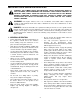
IMPORTANT SAFE OPERATION PRACTICES WARNING: THIS SYMBOL POINTS OUT IMPORTANT SAFETY INSTRUCTIONS WHICH, IF NOT FOLLOWED, COULD ENDANGER THE PERSONAL SAFETY AND/OR PROPERTY OF YOURSELF AND OTHERS. READ AND FOLLOW ALL INSTRUCTIONS IN THIS MANUAL BEFORE ATTEMPTING TO OPERATE YOUR UNIT. FAILURE TO COMPLY WITH THESE INSTRUCTIONS MAY RESULT IN PERSONAL INJURY. WHEN YOU SEE THIS SYMBOL, HEED ITS WARNING.
• Maintain the weight balance of the tractor. Install front end weights to counterbalance heavy implements attached to the three point hitch. Do not operate the tractor with a light front end. • Any towed vehicle with a total weight exceeding that of the tractor should be equipped its own braking system that is operational from the tractor seat. • Keep all movement on the slopes slow and gradual. Do not make sudden changes in speed or direction.
• Escaping hydraulic fluid under pressure can penetrate the skin. If fluid is injected into the skin, seek immediate medical attention. Do not use your hand to check for leaks. Use a piece of cardboard or paper. 5. SAFETY FRAME (ROPS) • Never run a machine inside a closed area. Your tractor is equipped with a rollover protective structure (ROPS) which must be maintained in a fully functional condition. Use care when driving through doorways or spaces with a low overhead.
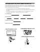
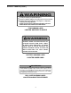
SAFETY LABELS STARTING INSTRUCTIONS IGNITION 1. KNOW THE OPERATING AND SAFETY INSTRUCTIONS IN THE OPERATORS'S MANUAL AND ON THE TRACTOR. 2. MOVE THROTTLE TO MID POSITION AND DEPRESS BRAKE PEDAL. 3. TURN KEY TO THE START POSITION. STOP STOPPING INSTRUCTIONS 1. DISENGAGE PTO AND SET PARKING BRAKE. 2. MOVE THROTTLE CONTROL TO MID POSITION AND TURN KEY OFF. WARN I N G AVOID SERIOUS INJURY OR DEATH. • • • • • • • • • • • GO UP AND DOWN SLOPES, NOT ACROSS. AVOID SUDDEN TURNS.
SAFETY LABELS (Cont.) WARNING To avoid personal injury, keep PTO shield in place. Pull only from draw bar. pulling from any other point can cause rear overturn. Disengage PTO and stop engine before servicing tractor, or implements, or attaching or detaching implements. FAILURE TO FOLLOW ANY OF THE INSTRUCTIONS ABOVE CAN CAUSE SERIOUS INJURY TO THE OPERATOR, OR OTHER PERSONS. PTO WARNING LABEL LOCATED ON REAR PTO SHIELD WARNING BATTER IES CON TAIN ACID AN D EX P LOS IV E GAS .
SECTION 1: CONTROLS AND FEATURES FLOORBOARD AND DASH PANEL MOUNTED CONTROLS N A B C M D L E K F J H G Figure 1 A B C D E F Steering Wheel PTO Switch Throttle Handle Ignition Switch Brake Pedal Forward/Reverse Pedal G H J K L M N Seat Adjustment Lever Differential Lock Pedal Parking Brake Lever Choke Control Knob Hazard Light Switch Headlight Switch Instrument Panel * Steering Wheel and Seat Phantomed For Clarity 9
NOTE: References to LEFT and RIGHT indicate OFF - The engine and electrical system is turned off. that side of the tractor when facing forward while seated in the drivers seat. Reference to FRONT indicates the grille end of the tractor; to REAR, the drawbar end. ON - The tractor electrical system is energized. START- The starter motor will turn the engine. Release the key immediately when the engine starts A. Steering Wheel The steering wheel is centered on the dash panel.
K. Choke Control Knob H. Differential Lock Pedal Choke Knob Diff. Lock Pedal Symbol Figure 8 Figure 6 Located at the rear of the left floor board, the differential lock pedal engages the transmission differential lock. The choke knob controls the position of the engine choke. Pull the knob out to choke the engine; push the knob in to open the choke. The differential lock is used to gain additional traction when operating the tractor on wet or loose soil.
N. Instrument Panel 4 3 5 6 7 2 1 Orange Line 8 10 9 Figure 11 1. Fuel Gauge 6. Parking Brake Indicator Light The fuel gauge, located on the left side of the instrument panel, monitors the fuel level in the fuel tank. The needle pointing to the right indicates a full tank. The ignition switch must be in the ON position to read the fuel gauge. The bulb illuminates when the ignition switch is in the ON position and the parking brake is engaged.
FENDER MOUNTED CONRTOLS AND FEATURES B A F C G D N E G M H H J L K K J Figure 12 A B C D E F G H J K L M N Fuel Fill Cap PTO Reverse Override Switch PTO Selection Lever Hydraulic Lift Lever Trans. Hi/Lo Shift Lever Cup Holder Hand Holds Amber Hazard Lights Tail Lights (Red) Reverse Lights (White) Storage Tray ROPS Seat Belt A. Fuel Fill Cap C. PTO Selection Lever The fuel fill cap is located on the left fender beside the operator’s seat.
EE. Transmission Hi/Lo Range Shift Lever J. Tail Lights The Hi/Lo range shift lever is located on the right fender. The lever has two speed range settings and a neutral position. The lever must be shifted into either the high or low range prior to depressing the forward/reverse pedal to drive the tractor. The tail lights illuminate when the ignition switch is in the ON position and the headlight switch is turned on. • Push the lever forward to shift into the high range.
SECTION 2: OPERATION ROLLOVER PROTECTIVE STRUCTURE (ROPS) FOLDING THE ROPS This tractor is equipped with a foldable Rollover Protection Structure (ROPS) and seat belts. When used together they are effective in reducing injuries to the operator in the event of an accidental tractor rollover. The safety provided by the ROPS is minimized if the seat belt is not properly adjusted AND buckled. Refer to ADJUSTMENTS for seat belt adjustment.
The fuel fill cap is located on the fender to the left of the seat. Unscrew the fuel cap and fill tank from an approved gasoline container. Immediately wipe up any spilled fuel. SAFETY INTERLOCK SYSTEM This tractor is equipped with a safety interlock system for the protection of the operator. If the interlock system should ever malfunction, do not operate the tractor. Contact your authorized Cub Cadet Dealer.
• • Move the throttle handle to midway between the “SLOW” and “FAST” position. Refer to Figure 15. COLD WEATHER STARTING Make sure the PTO switch is in the “OFF” position. Note: The PTO light on instrument panel will flash if switch is in ON position. • Follow the normal engine starting instructions above. THROTTLE HANDLE SLOW USING JUMPER CABLES TO START THE ENGINE WARNING: Batteries contain sulfuric acid and produce explosive gasses.
Operate the tractor up and down slopes, never across slopes. Do not drive so that the tractor may tip over sideways DRIVING THE TRACTOR WARNING: Avoid sudden starts, excessive speed and sudden stops. Before operating the tractor on a slope, walk the slope to look for possible hazards such as rocks, mounds, stumps, or surface irregularities which could cause the tractor to be upset. WARNING: Do not leave the seat of the tractor without disengaging the PTO and engaging the parking brake.
PARKING BRAKE LEVER LOW range — Forward speed 0 to 5.6 mph. Reverse speed 0 to 2.8 mph. Shift the lever fully rearward in the slot. Low range is recommended for use with most PTO driven tractor attachments. Low range must be used when climbing or descending slopes.
• Fully depress and hold the differential lock pedal to engage the transmission differential lock. Release the pedal to disengage the differential lock. See Figure 18. HYDRAULIC LIFT LEVER DIFFERENTIAL LOCK PEDAL (Depress and Hold to Engage) Highest Height Position Lowest Height Position Figure 19 USING THE PTO SELECTION LEVER The position of the PTO selection lever will determine whether the rear PTO, mid PTO, or both PTO’s will be engaged when the PTO switch is activated.
• USING THE PTO REVERSE OVERRIDE SWITCH Shift the PTO lever to the middle position to select both the mid PTO and rear PTO. The mid PTO and rear PTO will run simultaneously when the PTO switch is activated. The PTO reverse override switch, located on the left fender, allows the PTO to operate while the tractor is traveling in the reverse direction. Refer to Figure 20.
Read the ADJUSTMENTS section for instructions on adjusting the RH adjustable lift link, top hitch link, and hitch chain. See Figure 23. USING THE TOP LINK RETAINER HOOK The top link hook is provided to retain the the top link of the three point hitch when not in use. To utilize the top link hook, proceed as follows: • While holding the top link upward, raise the hook rod and slide it fully to the left so that it locks in the upright position in the right slot of the mounting bracket. See Figure 22.
Using the Auxiliary Hydraulic Control Handle USING THE AUXILIARY HYDRAULIC VALVE (IF EQUIPPED) Use the auxiliary hydraulic control handle located on the right fender as follows: Some tractors may be equipped with an auxiliary hydraulic valve package. This package provides two hydraulic circuits for operating optional equipment that can be installed on the tractor. • Pull the handle rearward to raise the front hitch or front loader boom. See Figure 25.
TRACTOR WEIGHTING Weighting the Rear of the Tractor When implements are installed on either the front or rear of the tractor, the normal balance of the tractor is altered. • As a rear mounted implement is raised to the transport position, the balance point of the tractor shifts rearward, which may result in a loss of steering control and tractor stability. Adding weight to the rear of the tractor is not required for most Cub Cadet front mounted equipment currently available for this tractor.
SECTION 3: ADJUSTMENTS Adjust the final length of the seat belt using the adjuster clip, buckle link, and upper belt webbing on the right half of the belt. ADJUSTING THE SEAT For the comfort of the operator, a single lever adjustable seat is provided to set the fore to aft position of the seat. Adjust the seat to the most comfortable position that allows you to operate all controls and pedals.
• • The length of the upper hitch link is normally determined by the design of each implement. To adjust the upper hitch link, loosen the locking lever and turn the adjustment tube as shown in Figure 29. After the appropriate length is attained, tighten the locking lever. If correctly adjusted, the upper hitch link will be parallel or nearly parallel to the lower hitch links. Distance ‘A’ should be 0"-.20" less than distance ‘B’ if the toe-in is correct. If it is not, readjust the toe-in.
ADJUSTING THE BRAKES • The tractor brakes are adjusted at the factory and should experience minimal wear if the tractor is operated normally. However, all brake pads are subject to wear and at some point the brake linkage may have to be adjusted. Turn the adjustment ferrule onto the rod as needed to shorten the rod and acquire the .160" minimum gap. • Reinstall the ferrule and internal cotter pin in the brake link. • Engage the parking brake and recheck the brake rod gaps.
SECTION 4: MAINTENANCE pressure lubricating gun to force in new grease. Apply pressure until clean grease emerges from the lubrication point. The service life and reliability of any machine depends upon the care it is given. Proper lubrication and maintenance is a vital part of that care. Using the Lubrication and Maintenance Chart as a guide, monitor the hourmeter on the instrument panel to ensure the required maintenance procedures are performed.
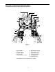
10 8 18 7 10 9 22 12 11 6 5 1 29 13 16 14 17 15 2 17 6 19 3 20 20 7 21 14 17 21 6 4 15 17 LUBRICATION AND MAINTENANCE CHART (ILLUSTRATION)
LUBRICATION AND MAINTENANCE CHART Check Engine Oil Level 2 Check Air Cleaner 3 Check Engine Coolant Level 4 Check and Clean Radiator Screen and Oil Cooler Fins 5 Clean Air Cleaner Foam Element 6 Change Engine Oil and Replace Oil Filter first 8 hrs. • Retorque Front and Rear Wheel Bolts first 10 hrs.
• ACCESSING THE ENGINE COMPARTMENT WARNING: If the tractor has been recently operated, engine surfaces (including the radiator) will be HOT. Allow the engine to cool before opening the hood, or use extreme caution to avoid burns when the hood is open. Pull the quick fastener tabs slightly outward and rotate 1/4 turn (perpendicular to slot) to lock the side panels in place. Flip the fastener tabs down.
• Because battery acid is corrosive, do not pour it into any sink or drain. Before discarding an empty electrolyte container, rinse it thoroughly with a neutralizing solution. • NEVER connect (or disconnect) battery charger clips to the battery while the charger is turned on, as it can cause sparks. • Keep all sources of ignition (cigarettes, matches, lighters) away from the battery. The hydrogen gas generated during charging can be combustible.
HEAD LIGHT BULB REPLACEMENT Replace a tail light bulb as follows: The tractor is equipped with four headlight bulbs. If one of the bulbs should burn out, replace the bulb as follows: • Turn the light socket counterclockwise to align the socket tabs with the notches in the tail light reflector. • Fully raise the hood so that the hood prop cylinders hold the hood in the raised position. • Once aligned, carefully pull the light socket out of the tail light reflector.
INSTRUMENT PANEL BULB REPLACEMENT Accessing the Fuse Center Referring to the instrument panel information provided in the CONTROL AND FEATURES section of this manual, regularly check to ensure that the instrument panel light bulbs are functioning. The fuse center is located on the inside right of the dash panel. To access the fuse center, remove the dash panel insert by removing the two screws. See Figure 42.
Main Fuse The main fuse in the tractor wire harness protects the tractor’s entire electrical system. A blown main fuse will prevent battery current from passing though the harness. FLASHER RELAY XX XX TAPE To replace the main fuse: • Raise the tractor hood and remove the right side panel. • Locate the main fuse under the dash panel, along the tractor’s right frame rail. See Figure 44. WIRE HARNESS HARNESS LEADS MAIN FUSE FUSE HOLDER RT.
• If the oil level is low, add Cub Cadet hydraulic oil. Loosely position a funnel in the fill hole so that there is enough clearance around the funnel to allow the transmission to vent while the oil is poured into the transmission. Fill ONLY to the full mark, never overfill the transmission. • Place a suitable container(s) beneath the front of the transmission housing.
CHANGING HYDROSTATIC TRANSMISSION AND HYDRAULIC SYSTEM OIL FILTERS • Position the collection container below the hydraulic system filter. See Figure 47. NOTE: With the exception of the first oil filter change after the 25 hour break-in period, the hydrostatic transmission and hydraulic system oil filters should be changed along with the hydrostatic transmission/hydraulic system oil after every 200 hours of operation.
CHECKING OIL LEVEL IN FRONT AXLE AND FINAL REDUCTION GEAR CASES. Check the front axle and final reduction gear case oil levels after every 50 hours of operation. Check the oil level only while the engine is stopped and the tractor is standing on a level surface. Check Front Axle Oil FILL PLUG The oil fill plug/dipstick is located on the left side of the axle housing. See Figure 48.
• The front end of the drive shaft can be accessed from under the hood, and the rear end by removing the six screws and the center fender cover. The drive shaft can also be accessed from the underside of the tractor. NOTE: It may be necessary to rotate the drive shaft to access the grease fittings. Fill the axle with Cub Cadet Gear Lube until the oil level reaches the full mark on the dipstick. Do not over fill the axle housing.
• TIRE MAINTENANCE Check the tire air pressure after every 50 hours of operation or weekly. Keep the tires inflated to the recommended pressures. Improper inflation will shorten the service life of a tire. See the tire side wall, or the Tire Inflation chart, for proper inflation pressures. Observe the following guidelines: • • TIRE INFLATION CHART Do not inflate a tire above the maximum pressure shown either on the sidewall of the tire or the Tire Inflation chart.
3. Clean the engine and the entire tractor thoroughly. • Add to clean, fresh gasoline the correct amount of stabilizer for the capacity (approximately 6 gallons) of the fuel system. 4. Drain and flush the cooling system. Refill with a minimum 50/50 antifreeze and water coolant solution. Use a higher percentage of antifreeze if the tractor will be subjected to temperatures below minus 30° F.
SECTION 5: ENGINE INFORMATION AND MAINTENANCE KAWASAKI LIMITED WARRANTY CALIFORNIA AND FEDERAL EMISSIONS CONTROL SYSTEMS SMALL OFF-ROAD ENGINES The California Air Resources Board, the Environmental Protection Agency (EPA) , and Kawasaki Motors Corp., U.S.A. (hereinafter “Kawasaki”) are pleased to explain the Emission Control Systems Warranty on your Kawasaki small off-road engine.
3. LIMITED LIABILITY. (a) The liability of Kawasaki under this Emission Control Systems Warranty is limited solely to the remedying of defects in materials or workmanship by any authorized Kawasaki small off-road engine dealer at its place of business during customary business hours. This warranty does not cover inconvenience or loss of use of the small off-road engine or transportation of the small off-road engine to or from the Kawasaki dealer.
cooling fins. Blow the debris out using compressed air directed from the fan shroud side of the radiator. ENGINE MAINTENANCE WARNING: Use care when servicing any component in the engine area. If the engine has recently been operated, components will be hot and could cause burns. Allow the engine to cool before servicing. Reinsert the screen, making sure that it is in the slots of the radiator frame.
ADDING ENGINE OIL WARNING: Never overfill the engine crankcase. The engine may overheat and/or damage may result if the crankcase is below the “ADD” mark or over the “FULL” mark on the dipstick. For best results, fill to the “FULL” mark on the dipstick as opposed to adding a given quantity of oil. Always check the level on the dipstick before adding more oil. • Place the tractor on a level surface and engage the parking brake. Stop the tractor engine and remove the ignition key.
• Turn the valve drain cock fully clockwise to close the valve, and clean any residual oil from the valve. Refer to Figure 56. • Raise the tractor hood and check the coolant level in the overflow reservoir on the left side of the engine. Refer to Figure 57. • Apply a light coating of clean oil on the gasket of the new oil filter. Thread the filter on by hand until the gasket contacts the filter mounting surface, then tighten the filter an additional 3/4 turn.
INSPECTION OF COOLING SYSTEM HOSES • Check the cooling system hoses for any cracks or deterioration every 200 hours of operation. Check all hose connections for looseness. Replace any damaged hoses and tighten any loose connections. In stages, SLOWLY pour the coolant solution into the filler neck, allowing as much air as possible to escape through the neck. Fill to the overflow flange of the filler neck.
SERVICING THE SPARK PLUGS SERVICING THE FOAM PRECLEANER Wash the foam precleaner every 25 hours of operation. Wash more often when operating under extremely dusty conditions. Replace the precleaner if torn or otherwise damaged. WARNING: To avoid possible injury, be sure the engine is off and has cooled before making any adjustments or repairs. Referring to Figure 60, wash the precleaner as follows: Check the spark plugs after every 100 hours of operation. Replace with new plugs if necessary.
SECTION 6: SPECIFICATIONS Engine Manufacturer. . . . . . . . . . . . . . . . . . . . . . . . . . . . . . . . . . . . . . . . . . . . . . . . . . . . . . . . . . Kawasaki Horsepower . . . . . . . . . . . . . . . . . . . . . . . . . . . . . . . . . . . . . . . . . . . . . . . . . . . . . . . . . . . . . . . 25 Cylinders . . . . . . . . . . . . . . . . . . . . . . . . . . . . . . . . . . . . . . . . . . . . . . . . . . . . . . . . . . . . . . . 2 OHV Cooling System. . . . . . . . . . . . . . . . . . . . . . .
SPECIFICATIONS Hydraulic Lift System Type . . . . . . . . . . . . . . . . . . . . . . . . . . . . . . . . . . . . . . . . . . . . . . . . . . . . . . . Auxiliary Pump-Gear Control . . . . . . . . . . . . . . . . . . . . . . . . . . . . . . . . . . . . . . . . . . . . . . . . . . . . Position Control Lever Pump Capacity . . . . . . . . . . . . . . . . . . . . . . . . . . . . . . . . . . . . . . . . . . . . . . . . . . . . . . . 8 gal./min. Maximum Pressure . . . . . . . . . . . . . . . . . . . . . . . . . .
SECTION 7: OPTIONAL EQUIPMENT AND ACCESSORIES When purchasing your tractor, you probably had it equipped for your particular needs at that time. You may later wish to obtain additional equipment or accessories to perform other tasks. Refer to the chart below for a list of optional equipment and accessories currently available through your Cub Cadet dealer.
LIMITED WARRANTY FOR CUB CADET COMPACT TRACTORS AND CUB CADET ATTACHMENTS Proper maintenance of your Cub Cadet equipment is the owner’s responsibility. Follow the instructions in your owner’s manual for correct lubricants and maintenance schedule. Your Cub Cadet dealer carries a complete line of genuine Cub Cadet parts and quality lubricants and filters for your equipment’s engine, transmission, chassis and attachments.