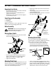
Operator’s Manual Single Stage Snow Thrower Model 721E IMPORTANT: Read safety rules and instructions carefully before operating equipment. Warning: This unit is equipped with an internal combustion engine and should not be used on or near any unimproved forestcovered, brush-covered or grass-covered land unless the engine’s exhaust system is equipped with a spark arrester meeting applicable local or state laws (if any).
TABLE OF CONTENTS Content Page Important Safe Operation Practices .................................................................................. 3 Assembling Your Snow Thrower ....................................................................................... 5 Know Your Snow Thrower................................................................................................. 6 Operating Your Snow Thrower ..........................................................................................
SECTION 1: IMPORTANT SAFE OPERATION PRACTICES WARNING: This symbol points out important safety instructions which, if not followed, could endanger the personal safety and/or property of yourself and others. Read and follow all instructions in this manual before attempting to operate this machine. Failure to comply with these instructions may result in personal injury. When you see this symbol—heed its warning.
5. 6. 7. 8. 9. 10. 11. 12. 13. 14. 15. 16. 17. 18. 19. 20. Maintenance And Storage Never operate with a missing or damaged discharge chute. Keep all safety devices in place and working. Never run an engine indoors or in a poorly ventilated area. Engine exhaust contains carbon monoxide, an odorless and deadly gas. Do not operate machine while under the influence of alcohol or drugs. Muffler and engine become hot and can cause a burn. Do not touch.
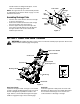
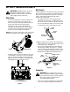
SECTION 2: ASSEMBLING YOUR SNOW THROWER Unpacking From Carton • • • • Cut along corners of the carton and lay it down flat. Remove packing material. Remove any loose parts included with unit (i.e., operator’s manual, etc.). Roll unit out of carton. Check carton thoroughly for any remaining loose part. • • Remove the hairpin clip from the end of the lower chute crank. Insert the upper chute crank into the lower chute crank and align the holes.
handle. Hold the “Z” fitting with the pliers, not the cable, to avoid damaging the cable. Lower Chute Nut NOTE: The upper hole in the control handle provides for adjustment in belt tension. Refer to page 9 of this manual for instructions. Carriage Bolt Flat Washer Flat Washer Assembling Discharge Chute • • • Hex Bolt Turn the chute crank until the chute faces straight to the front. See Figure 4 . Remove the hand knob, flat washer and carriage bolt from the upper chute. See Figure 4.
Discharge Chute Ignition Key The angle of the discharge chute controls the distance that the snow is thrown. Tilt the discharge chute up for greater distance; tilt down for less distance. Loosen the hand knob on the side of the discharge chute to adjust. Tilt the chute to the desired position, and tighten the knob. Used to start engine. Put key in “ON” position to start for both electric and recoil start engines. Follow starting instructions given in the next section.
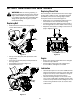
• • • • • • If you have a grounded three-prong receptacle, proceed as follows. Rotate choke lever to FULL position. Connect power cord to switch box on dash panel. Plug the other end of power cord into a three-prong 120-volt, grounded, AC receptacle. Push starter button to crank engine. As you crank the engine, move choke lever to FULL choke position. When engine starts, release starter button, and move choke gradually to OFF. If engine falters, move choke immediately to FULL and then gradually to OFF.
SECTION 5: MAKING ADJUSTMENTS Belt Tension WARNING: NEVER attempt to make any Periodic adjustment of the belt tension may be required due to normal stretch and wear on the belt. Adjust the belt tension, following instructions below, if the augers seem to hesitate while turning although engine maintains the same speed. adjustments while the engine is running, except where specified in the snow thrower and/or engine operator’s manuals.
SECTION 6: MAINTAINING YOUR SNOW THROWER Replacing Shave Plate WARNING: Before servicing, repairing, or The shave plate is attached to the bottom of the auger housing and is subject to wear. It should be checked periodically. There are two wearing edges and the shave plate can be reversed. See Figure 14. inspecting, disengage all clutch levers and stop engine. Wait until all moving parts have come to a complete stop.
SECTION 7: OFF-SEASON STORAGE • • WARNING: Never store engine with fuel in tank indoors or in enclosed, poorly ventilated areas where fuel fumes may reach an open flame, spark or pilot light as on a furnace, water heater, clothes dryer, or other gas appliance. • • Follow “Storage” instructions in the Engine Manual. Store in a clean, dry area. Block the snow thrower up so it is not resting on the rubber auger blades.
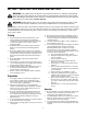
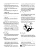
SECTION 9: PARTS LIST FOR MODEL 721E 15 9 6 21 6 17 14 6 21 24 21 23 3 1 8 22 10 13 4 2 20 25 16 7 33 32 35 47 11 57 42 12 19 48 45 18 31 44 26 58 11 35 53 41 49 60 36 5 5 42 28 52 33 27 37 29 59 5 54 49 56 40 50 51 35 43 53 38 34 46 55 39 30 12
Model 721E Ref. No. 1. 2. 3. 4. 5. 6. 7. 8. 9. 10. 11. 12. 13. 14. 15. 16. 17. 18. 19. 20. 21. 22. 23. 24. 25. 26. 27. 28. 29. 30. Part No. Part Description 684-0174 Upper Chute Crank Assemby 684-0177 Lower Chute Crank Assembly 684-0178 Bracket Assembly: Mitten Grip 684-0192 Shroud:Black, 7 Hp. Electric 710-0895 TT Screw 1/4-15 x 0.75” 710-1003 B Screw #10-16 x 0.625” 710-1882 Hex Flange Screw 710-3083 Hex Bolt 5/16-18 x 1.
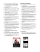
Model 721E 19 16 24 18 1 15 7 5 11 10 15 8 17 Engine is for reference only and may not resemble the engine on your snow thrower. 9 6 13 25 3 21 13 23 14 3 2 4 22 Ref. No. 1. 2. 3. 4. 5. 6. 7. 8. Part No. 629-0236 Description Extension Cord 710-0157 Hex Bolt 5/16-24 x 0.75” 710-0409 Hex Bolt 5/16-24 x 1.75” 710-0502A TT Sems Screw 710-0751 Hex Screw 1/4-20 x 0.620” 710-1003 B Screw #10-16 x 0.625” 710-3013 Hex Screw 1/4-20 x 0.50” 712-3006 Hex Nut 1/4-20 Ref. No. 9. 10.
Model 721E 5 Ref. No. 9 8 10 3 2 4 710-0487 Carriage Screw 5/16-18 x 2.0” 2. 710-1270 Machine Screw 3. 712-0324 Hex Lock Nut 1/4-20 4. 720-0284 Hand Knob w/ Wing Nut 5. 720-0295 Foam Grip 6. 725-0157 Cable Tie 7. 736-0451 Saddle Washer 8. 746-0883 Control Housing 9. 747-0956 Auger Bail 749-0711A Upper Handle: Gull Wing NOTE: For painted parts, please refer to the list of color codes below.
MANUFACTURER’S LIMITED WARRANTY FOR: TWO-YEAR RESIDENTIAL ONE-YEAR COMMERCIAL Proper maintenance of your Cub Cadet equipment is the owner’s responsibility. Follow the instructions in your operator’s manual for correct lubricants and maintenance schedule. Your Cub Cadet dealer carries a complete line of quality lubricants and filters for your equipment’s engine, transmission, chassis and attachments.