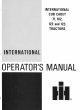
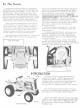
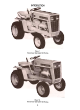
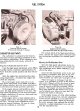
1 INTRODUCTION Illust. Internatianal 1 Cub Cadet 122 Tractor. Illust. 1A International Cub Cadet 102 Tractor.
FRONT REARPQWERTAKE-OFF ENGINE FRONT ELECTRICALSYSTEM PNEUMATIC CLUTCH STORING CLEANER. ACCESSORIES AIR AND OPERATING HITCHING FUEL DRIVINGTHETRACTOR SYSTEM. TRAILING THE AND TAKE-OFF TABLE. GUIDE. TRACTOR BRAKE. TIRES. THE AND COOLING POWER WHEELS. EQUIPMENT LUBRICATION LUBRICATION EXTRA LUBRICATION. TROUBLESHOOTING INDEX. SPECIFICATIONS. ENGINE EQUIPMENT . TRACTOR NEW YOUR CONTROLS. AND OPERATING INSTRUMENTS CONTENTS. INTRODUCTION. BEFORE INTRODUCTION Illust.
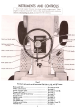
Illust. 3 Instruments and contrals on the International Cub Cadet 71, 102, and 122 Tractors. Brakepedallock Choke control button See pages 8 and 9. .See page 6. Clutch and broke pedal Creeper shift lever. Front power toke-off clutch lever.. See pages 21 and 22. See page 9. See page 13. Gearshift lever Ignition switch lift handle Lifthandlestop Lighting switch button. Throttle lever. See page 9. Seepage 14. Seepage 11. Seepage 11. See pages 14 and 17. See page 5.
BEFORE OPERATING YOUR NEW TRACTOR Lubrication. Lubricate the entire tractor. Check the air pressure. Fuel system. Fill Seepages26 ta 32. Seepages20 and21. the fuel tank with gasoline. Seepage6. Illust.5 Fuel system and contrals (International on International Cub Cadet Cub Cadet 71, 102 and 122 Tractars 123 Tractor. are similar.) THROTTLE LEVER LIFTING THE HOOD This lever controls the speed of the engine.
THE ENGINE control button all the way in. Do not use thechoke to enrich the fuel mixture, except when necessary to start the engine. STARTINGTHE ENGINE Be sure the fuel shut-off valve is open. Manual Starting: (Tractors without electric starting). Raise the tractor hood. The retractable starter is mounted on a support plate at the front of the engine at the right side of thetractor. 2. Pull the choke control button all the way out (see Illust. 3 or 4).
FUELSYSTEM Carburetor (International Illust. 7 and fuel strainer. Cub Cadet 71 Tractor) Illust.7A Carburetor and fuel strainer. (Internationol Cub Cadet 102, 122 and 123 Tractors) CARBURETORADJUSTMENTS For a final ment, operate any corrections tion. The carburetor is adjusted at the factory and under normal operating conditions it will not require readjusting.
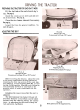
PREPARING THE TRACTOR FOR EACH DAY'S WORK Fill run. the fuel tank at the end of each day's See page 6. Check the crankcase oil level oil if necessary. Seepage 26. Clean the air cleaner element and add new if necessary. See page 14. Inspect the tires for general condition. See pages 20 and 21. ADJUSTINGTHE SEAT Illust. SA Adjusting the seat. (International Cub Cadet 102 Tractor.) Illust. 88 Adju sting the seat. (Internatianal (Intemational Cub Cadet 71 Tractar.) Illust.
DRIVING THE TRACTOR (International Cub Cadet 71, 102 and 122 Tractors) CLUTCHAND BRAKE PEDAL Note: Do not rest your foot on the pedalwhile driving the tractor, as this will result in excessive clutch lining wear. The combination clutch and brake pedal is used to disengage the engine from the transmission when shifting gears and to actuate the brake to stop the tractor. The pedal must be pressed all the way down to activate the safety starting switch when starting the engine.
DRIVING THE TRACTOR (International Cub Cadet 123 Tractor) BRAKE PEDAL Hote: Do not rest your foot on the brake pedal while driving the tractor as this wouldcause the speed control lever to return to the "N" position. The brake pedal must -be pressed all the way down to activate the safety starting switch. When the brake pedal is in the depressed position it automatically moves the speed control lever to the "N" position.
HITCHING TRAILING EQUIPMENT TO THE TRACTOR Illust. 11A Drawbar and three-paint hitch. (International Cub Cadet 102. 122 and 123 Tractors) Illust. 11 Drawbar and three-point hitch International shown on Cub Cadet 71 Tractor. LIFT HANDLE This handle is used to lift or lower equipment used with the tractor. Depress the release button to move the handle. When operating equipment position, depress the release the handle and move the wire of the button. SeeIllust. 118.
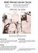
5. REAR POWER TAKE-OFF (International Cub Cadet 71, 102 and 122 Tractors) Illust. 12 Operating Internatianal the Pawer Take.aff. Cub Cadet 71 Tractar Itlust.12A Operating Internatianal If your tractor is equipped with a rear power take-off, the following instructions and precautions should be carefully studied and followed. The rear power take-off is started and stopped by the same engine clutch as the tractor.
After considerable clutch use, it may be necessary to readjust the button clearance as described below to assure proper clutch disengagement. OPERATINGTHE FRONTPOWERTAKE.OFF CLUTCH 1. Move the throttle or low idle speed. lever back to medium 2. Move the front power take-off clutch lever (forward) to the engaged position (rearward) to the disengaged position. See Illusts.
the ENGINECOOLING This tractor has an air cooled engine. Air must be able to circulate freely around the engine, through the screen and shroud, and over the fins of the cylinder head and cylinderblock. Keep these areas free of accumulated dirt and trash or the engine will overheat and result in damaged moving parts. DRY-TYPE AIR CLEANER Incoming air for combustion is filtered by a dry-type air cleaner having a filter element inside of the cover.
ELECTRICALSYSTEM SPARKPLUG IGNITIONTIMING Note: Remove all dirt from the base of the spark plug before removing the spark plug. Remove the spark plug after every 100 hours of operation for cleaning and checking the gap. See Illust. 15. When making this adjustment, always bend the outer electrode. Never bend the center electrode, as it may damag:! the insulator. If the gap between the electrodes is too great, the engine will misfire and be hard to start. Illust.15A Adjusting the breaker paints.
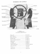
ELECTRICAL SYSTEM and Replacing The motor-generator (IZ-volt, negative ground) will function as a cranking motor when the ignition key is turned to the "START" position, driving the engine by means of abelt. When the engine is operating, function as a generator. the unit will the Motor-Generator Belt Replace the motor-generator belt when it becomes badly worn. To remove the old belt, loosen the motor-generator brace bolt I'A" and mounting bolt.s lIB", Illust.17.
ELECTRICAL SYSTEM Illust. an the 17 Electrical units right Electrical Illust.17A units on the left side of the tractor. 17 side of the tractor.
ELECTRICAL SYSTEM Index to reference numbers shown in Illust. Ref. No. Ref. No. Description Key ignition switch. Cable -ignition coil positive to key ignition switch "IGN" 10 (+) terminal terminal - 4 5 12 Cable -magnetic switch to key ignition switch "BAT" terminal -light green. Safety starting switch. Cable -safety starting switch to key ignition switch "ST" terminal - 13 14 15 16 17 orange. 6 Cable -safety starting switch to magnetic switch -orange w/black 7 Magnetic switch.
FRONT WHEEL TOE-IN Illust.20 Front wheel adjustments. Illust.20A Tie rod and drog link boll joints. The front wheel inch to 1/8-inch toe-in toe-in dimension (1/32-inch the lock nut, and turn the tie rod ball joint end in or out as required. is 1-32- to 1/8-inch closer in front than in the rear). Measure the distance between two points "A" and two points "B" Illust. 20.
PNEUMATIC TIRES OPERATINGPRESSUREFORTIRES REAR WHEELWEIGHTS Rear wheel weights increase traction and reduce wheel slippage. The weights weigh approximately 26 pounds each. They are attached to each rear wheel with two bolts, lock washers, and hex. nuts. Inflate the front and rear tires for normal or heavy load operations as shown in the fol- lowing table. If additional weight is desired. a second set of weights can be attached to each first weight by using two longer bolts.
CLUTCH AND BRAKE (International Cub Cadet 71, 102 and 122 Tractors) As the clutch and brake are both operated by the same pedal, care must be taken to maintain a neutral zone so the clutch is disengaged when the brake is applied. ADJUSTINGTHE CLUTCH It is important that a clearance of .050inch be maintained between the clutch release lever and the clutch release bearing. In order to maintain this clearance. the pedal should have a free movement of approximately 3/16inch. SeeIllust. 21.
BRAKE (International Cub Cadet 123 Tractor) Speed control lever centering ~ zone when brake pedal is used Top surface of pedal foot pad Speed control lever in "N" position Pedalreturnstop """'" '-- Braking zone: Brake must be engaged .' when pedal is in this zone. Foot s~pport~.. 1-5/16-inch maximum Brake pedal must be fully engaged when, arm reaches this position. () I J ~ 3/4 -inch minimum, ! ~~j i Pedal stop '-..J A-86719 A Illust.23 Brake adjustments.
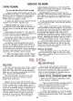
When 71 STORAGE Store your tractor Leaving your in a dry and protectedplace. tractor outdoors, ex- battery at least once a month for water and amount of charge. Seepage19. posed to the elements. will result in materially shortening its life. storing level 6. On the International Cub Cadet 71, 102 and 122 Tractors press the clutch and brake pedal all the way down and engage the brake pedal lock. This will prevent the clutch lining from sticking to the pressure plate. the tractor: 1.
TROUBLE SHOOTING Possible Possible Cause Remedy LACK OF POWER -Continued Incorrect Clutch slipping timing (Models or faulty 71,102 ignition. and See .'Breaker 122) Points and Spark Plug" on poges 15 and16. Adjust the free travel of the pedal; see pages 21 and22. Brake drags. Adjust the brake; see pages 21 ond 22. ENGINEOVERHEATS Insufficient shroud, cool air, dirty or cooling fins. air intake screen, Keep the air See "Engine on poge 14.
LUBRICATION GUIDE (International Cub Cadet 71, 102 and 122 Tractors) --After Every 10 Hours of Operation 1 -Oi I fi lief ca p and bayanet-type oil level gauge. Check the oil (with the engine stopped) and add sufficient new oil to bring it to the "FULL" mark on the gauge. Do not overfill. Do not operate the engine if the oil level is below the "LOW" mark on the gauge. 2- Steering knuckles (2). 3- Front oxle pivot pin.
2. 5. 8. LUBRICATION GUIDE (International Cub Cadet 123 Tractor) --After 1. Oil filler cap and bayonet-type oj I level gauge. Every 10 Hours of Operotion Check the oil (with the engine stopped) and add sufficient new oil to bring it to the "FULL" mark on the gauge. Do not overfill. Do not operate the engine if the oil level is below the "LOW" mark on the gauge. 3. Front axle pivot pin.
MEMORANDA 36
with No accident-prevention cessful without program can be suc- the wholehearted co-operation of the person who is directly responsible operation of equipment. To read accident of accidents accident reports it.