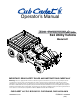
Operator’s Manual 6x4 Utility Vehicle Model 641 IMPORTANT: READ SAFETY RULES AND INSTRUCTIONS CAREFULLY Warning: This unit is equipped with an internal combustion engine and should not be used on or near any unimproved forestcovered, brush-covered or grass-covered land unless the engine’s exhaust system is equipped with a spark arrester meeting applicable local or state laws (if any). If a spark arrester is used, it should be maintained in effective working order by the operator.
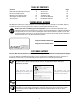
TABLE OF CONTENTS Content Important Safe Operation Practices Know Your Utility Vehicle Operating Your Utility Vehicle Servicing Your Utility Vehicle Service Chart Content Accessories Specifications Troubleshooting Commercial Warranty Residential Warranty Page 3 7 10 12 18 Page 18 19 19 23 24 FINDING MODEL NUMBER This Operator’s Manual is an important part of your new utility vehicle. It will help you assemble, prepare and maintain the unit for best performance. Please read and understand what it says.
SECTION 1: IMPORTANT SAFE OPERATION PRACTICES WARNING: This symbol points out important safety instructions which, if not followed, could endanger the personal safety and/or property of yourself and others. Read and follow all instructions in this manual before attempting to operate or service this vehicle. When you see this symbol - heed its warning.
Children 25. Do not start or operate vehicle in an inside area, unless it is adequately ventilated. Engine exhaust contains carbon monoxide fumes, which are very poisonous and can be deadly. 26. Do not change engine governor setting or over speed the engine. The governor is set at the factory for safe operating speed. 27. Assure safety interlock switch is adjusted correctly so engine cannot be started unless gearshift is in the neutral position. 28.
3. When manually raising cargo box, make sure Manual Support Lift Rod is securely locked before leaning under raised cargo box. 4. Do not operate vehicle with cargo box in raised position. 5. Do not operate vehicle with cargo box latch unlatched. Always re-latch upon manually lowering cargo box. 6. When using optional electric lift: • Stay in driver’s seat. • Keep body parts away from cargo box and keep all bystanders away.
WARNING • This is an off-road utility vehicle. Do not operate on public highways. It handles and maneuvers differently than a normal passenger car. Sharp, high speed turns or abrupt maneuvers can cause vehicle to roll over or go out of control. • Handling and maneuvering characteristics of vehicle change depending upon cargo load. Heavy loads will affect steering, braking, stability and overall handling of vehicle. • Read and understand operator's manual before operating vehicle.
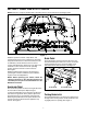
SECTION 2: KNOW YOUR UTILITY VEHICLE NOTE: Reference to right or left hand side of the utility vehicle is observed from the operating position. Figure 1 Brake Pedal Read this operator’s manual, safety labels, and operating instructions on the vehicle before operating. Compare the illustrations in this manual with your unit to familiarize yourself with the location of various controls and adjustments. Reference to the right or left hand side of unit is observed from the operating position.
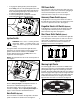
• • 12V Power Outlet To engage the parking brake, push brake pedal down firmly, pull out on the parking brake latch, and release foot from brake pedal. Brake pedal will stay down and parking brake light on dash will come on to indicate parking brake is engaged. To release parking brake, push down on brake pedal and parking brake latch will release. The 12V power outlet is located on the right side of the dash panel.
Hour Meter Fuel Shut Off Valve The hour meter is located in the center of the warning light cluster. It reads the elapsed time engine has run. See Figure 6. The fuel shut off valve is located under the seat and it is strapped onto the fuel tank. It controls fuel to the engine. To turn fuel off, turn knob so indicator is down. To turn fuel on, turn knob to the up position. See Figure 9. NOTE: The hour meter initially displays the battery voltage when you first turn it on.
WARNING: Do not exceed the vehicle’s Total Load Capacity of 1,400 lb., which includes driver, accessories, and cargo. Do not exceed 1000 lbs. in the cargo box. Cargo Box Tailgate The tailgate can be hinged at the top or the bottom depending on how you release the holding pins. If you pull out on the two top pins, the tailgate will swing down. If you pull out the two bottom pins, you can pivot the tailgate upwards.
Manual Lift WARNING: Do not stop or start suddenly when going uphill or downhill. Be especially cautious when changing direction on slopes. Apply brakes when going down slopes to maintain control of vehicle. • • NOTE: The manual lift and lower procedures should only be done after cargo box is emptied. • Release brake pedal and apply pressure to the accelerator pedal. Release accelerator and apply brake pedal evenly and firmly to slow down or stop.
Towing Loads WARNING: A loaded cargo box can be very heavy. Do not attempt to dump a loaded cargo box unless vehicle is equipped with an electric lift option. WARNING: To help prevent personal injury due to loss of control or tipping, always tow a load slowly enough to maintain control. IMPORTANT: If dumping by electric lift, stop immediately if actuator clutch slippage occurs. Lower cargo box completely and remove excess load by hand before dumping. • • • Reconnect the tailgate to the cargo box.
Engine • • Read the Engine operator’s manual for any service or maintenance information pertaining to the engine. • Filling Fuel Tank • • • • • • • Stop the vehicle on a level surface and apply parking brake. Turn the ignition key to the STOP position and remove the key. Allow engine to cool several minutes before you add fuel. Clean area around fuel cap and remove cap. See Figure 13. Fill tank with fresh, unleaded, regular grade fuel only to bottom of filler neck. Use a minimum of 87 octane.
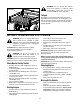
Replacing Headlights Wheel Replacement Headlights WARNING: Using an unstable lifting device and vehicle support may result in bodily injury. Use a safe lifting device and supports to work on raised vehicle. The headlights are held in place by a rubber seal around the perimeter of the headlight which creates a snug fit onto the fender. See Figure 15. • • • Remove the headlight by pulling it out of the fender. Disconnect headlight from wire connector.
• NOTE: Drive chain is set taught at the factory, so it will not reach normal stretch limits until vehicle has experienced reasonable hours of operation (50 hrs). • • • • • • • • • • • Stop vehicle on level surface, but do not apply parking brake. Put transmission in neutral and differential in the disengaged position. Turn the ignition key to the STOP position and remove the key. Use a safe lifting device to raise all four rear wheels off ground and place jack stands or wooden blocks under vehicle.
Adjusting Brake • Park vehicle on level surface and apply parking brake. • Raise and secure cargo box, if manual lift. • Rotate and inspect belt for wear or damage. • Measure width of belt on top surface. The width should be a minimum of 1.1 (27 mm). • Replace belt if worn beyond limit. To replace belt: • The wet brake system is an internal part of the transmission and it is adjusted externally without opening the transmission. There are two sets of brakes that may require adjustment.
Adjusting Throttle Pedal • • The throttle pedal assembly can be adjusted for comfort slightly higher or lower by lining up the holes of the lower pedal assembly with either the upper two or lower two holes of the upper pedal assembly. See Figure 21. • • Brake Pedal Assembly • • (Shown for reference) • • • • Line up here Lower Pedal Assembly OR Allow vehicle to cool. Replace all worn, damaged, or missing parts and tighten loose hardware as needed.
SECTION 5: SERVICE CHART Before Each Use First 10 Hours Every 50 Hours Every 100 Hours Every 500 Hrs or 2 years Check Transaxle Oil Change Transaxle Oil Tighten Wheel Bolts Drive Chain Tension Check Drive Belt Grease Front Steering Spindle Grease Axle Shaft U-Joints Grease Rear & Center Arms Grease Chain & Rollers Check Interlock Switch System Replace Interlock Switch Description Cart (20 Cubic Ft.
SECTION 7: SPECIFICATIONS Engine and Electrical Make HP Type Cylinders Valves Displacement Maximum Torque Ignition Lubrication Oil Filter RPM, idle (no load) RPM, fast (no load) Cooling System Air Cleaner Battery Alternator Headlights Wiring Kohler 20 HP 4-Cycle Gas 2 Overhead 38 cu. in. (624cc) 32.6 lb-ft @ 2600 rpm Transistor Controlled Full Pressure Replaceable (standard) 1250 ± 50 3950 ± 75 Air Heavy Duty, Replaceable, Dual Element 30-amp/hr, 365 cold cranking amps 12V-20amp Regulated Two 37.
SECTION 8: TROUBLESHOOTING Trouble Possible Cause(s) Trouble Possible Cause(s) Engine will not start Battery has low voltage. Loose or corroded battery connections. Fusible link is melted. Spark plug wire is loose or disconnected. Faulty spark plug or coil. Fuel shut-off valve turned off. No Fuel or improper fuel. Plugged fuel filter. Defective starter solenoid. Open-circuit in wiring. Engine is cold. Plugged fuel filter. Carburetor not adjusted properly or dirty. Engine oil viscosity too heavy.
NOTES 21
NOTES 22
CUB CADET CORPORATION MANUFACTURER’S ONE YEAR LIMITED WARRANTY (COMMERCIAL USE) The limited warranty set forth below is given by CUB CADET LLC (“CUB CADET”) with respect to new merchandise purchased and used in the United States, its possessions and territories.
MANUFACTURER’S LIMITED WARRANTY FOR: (RESIDENTIAL USE) The limited warranty set forth below is given by Cub Cadet LLC with respect to new merchandise purchased and used in the United States, its possessions and territories. “Cub Cadet” warrants this product against defects in material and workmanship for a period of two (2) years commencing on the date of original purchase and will, at its option, repair or replace, free of charge, any part found to be defective in materials or workmanship.