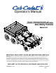
Operator’s Manual 6x4 Utility Vehicle Model 641 IMPORTANT: READ SAFETY RULES AND INSTRUCTIONS CAREFULLY Warning: This unit is equipped with an internal combustion engine and should not be used on or near any unimproved forestcovered, brush-covered or grass-covered land unless the engine’s exhaust system is equipped with a spark arrester meeting applicable local or state laws (if any). If a spark arrester is used, it should be maintained in effective working order by the operator.
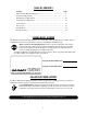
TABLE OF CONTENTS Content Page Important Safe Operation Practices................................................................... 3 Know Your Utility Vehicle ................................................................................... 7 Operating Your Utility Vehicle ............................................................................ 10 Servicing Your Utility Vehicle ............................................................................. 12 Service Chart ..........................
SECTION 1: IMPORTANT SAFE OPERATION PRACTICES WARNING: This symbol points out important safety instructions which, if not followed, could endanger the personal safety and/or property of yourself and others. Read and follow all instructions in this manual before attempting to operate or service this vehicle. When you see this symbol - heed its warning.
Children 25. Do not start or operate vehicle in an inside area, unless it is adequately ventilated. Engine exhaust contains carbon monoxide fumes, which are very poisonous and can be deadly. 26. Do not change engine governor setting or over speed the engine. The governor is set at the factory for safe operating speed. 27. Assure safety interlock switch is adjusted correctly so engine cannot be started unless gearshift is in the neutral position. 28.
3. When manually raising cargo box, make sure Manual Support Lift Rod is securely locked before leaning under raised cargo box. 4. Do not operate vehicle with cargo box in raised position. 5. Do not operate vehicle with cargo box latch unlatched. Always re-latch upon manually lowering cargo box. 6. When using optional electric lift: • Stay in driver’s seat. • Keep body parts away from cargo box and keep all bystanders away.
WARNING • This is an off-road utility vehicle. Do not operate on public highways. It handles and maneuvers differently than a normal passenger car. Sharp, high speed turns or abrupt maneuvers can cause vehicle to roll over or go out of control. • Handling and maneuvering characteristics of vehicle change depending upon cargo load. Heavy loads will affect steering, braking, stability and overall handling of vehicle. • Read and understand operator's manual before operating vehicle.
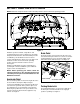
SECTION 2: KNOW YOUR UTILITY VEHICLE NOTE: Reference to right or left hand side of the utility vehicle is observed from the operating position. Figure 1 Brake Pedal Read this operator’s manual, safety labels, and operating instructions on the vehicle before operating. Compare the illustrations in this manual with your unit to familiarize yourself with the location of various controls and adjustments. Reference to the right or left hand side of unit is observed from the operating position.
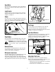
• • 12V Power Outlet To engage the parking brake, push brake pedal down firmly, pull out on the parking brake latch, and release foot from brake pedal. Brake pedal will stay down and parking brake light on dash will come on to indicate parking brake is engaged. To release parking brake, push down on brake pedal and parking brake latch will release. The 12V power outlet is located on the right side of the dash panel.
Hour Meter Engaged The hour meter is located in the center of the warning light cluster. It reads the elapsed time engine has run. See Figure 6. Light Switch The light switch is located on the left side of the dash panel. Push in top/bottom of switch to activate or turn off lights. See Figure 7. Choke The choke lever is located on the left side of the dash panel. The choke is used when starting a cold engine. It richens the fuel mixture for cold weather starting. See Figure 7.
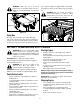
to the engine is capable. If equipped with a electrical lift, the cargo box can be raised to dump cargo. See Figure 11. WARNING: Make sure seat is in locked position prior to operation and do not try to adjust the seat position while operating the vehicle. WARNING: Do not exceed the vehicle’s Total Load Capacity of 1,400 lb., which includes driver, accessories, and cargo. Do not exceed 1,000lb. in the cargo box. Cargo Box Seat Lever Figure 10 Cargo Box The cargo box is raised by a gas spring.
Driving Utility Vehicle • • Electric Lift (Optional) • • Make sure front wheels are turned to the desired direction. Depress brake pedal to release parking brake. To avoid damaging transmission, depress brake pedal fully and make sure vehicle is completely stopped before shifting into Forward or Reverse. • • WARNING: Do not stop or start suddenly when going uphill or downhill. Be especially cautious when changing direction on slopes. Apply brakes when going down slopes to maintain control of vehicle.
• • Reconnect the tailgate to the cargo box. Do not drive the vehicle with cargo box in the raised position. • Loading the Cargo Box • • WARNING: The utility vehicle may become unstable if the cargo box is loaded incorrectly. Avoid loose and shifting loads or uneven loading of material. • • • • • • • • Verify cargo box is latched before loading. Securely anchor all loads in cargo box and do not load beyond maximum capacity. The maximum box capacity is 1000 lbs (454.5 kg).
• • • • • Jumping a Battery Turn the ignition key to the STOP position and remove the key. Allow engine to cool several minutes before you add fuel. Clean area around fuel cap and remove cap. See Figure 13. Fill tank with fresh, stabilized fuel only to bottom of the filler neck. Install fuel tank cap. WARNING: Do not attempt to jump start a frozen battery. Warm to 16 degrees C (60 degrees F). Do not smoke near battery and wear eye protection and gloves when handling battery.
• • Reassembly in reverse order. • Turn the ignition key to the STOP position and remove the key. Loosen but do not remove the five wheel bolts from the axle hub. See Figure 16. Wheel Bolts Headlight Lens & Housing Figure 15 Figure 16 Replacing Warning Lights • • • • Remove wing nuts. Raise hood to get access to under the dash panel. Remove the appropriate bulb socket and replace bulb. Reattach socket and lower hood. Secure hood to fender.
• • • • • • Use a safe lifting device to raise all four rear wheels off ground and place jack stands or wooden blocks under vehicle. Raise and secure cargo box, if manual lift. Rotate wheels toward or away from each other and check to see if there is any slack in the chain. See Figure 17. If the chain adjusters are not keeping the chain tight, a1/2 link will need to be removed. If chain is still loose after the 1/2 link is already removed, the chain should be replaced using a 98 to 99 link chain.
To adjust the brakes: • Park vehicle on level surface and apply parking brake. • Raise and secure cargo box, if manual lift. • Rotate and inspect belt for wear or damage. • Measure width of belt on top surface. The width should be a minimum of 1.1 (27 mm). • Replace belt if worn beyond limit. To replace belt: • • • • • Remove hardware and belt shield. See Figure 19. Belt Shield Clutch Pulley (Front) • • Stop the vehicle on a level surface.
• • • • • • • • • Prepare fuel system for storage. Replace all worn, damaged, or missing parts and tighten loose hardware as needed. Wash the vehicle and clean inside the engine compartment and under the cargo box. Run engine for several minutes to dry belts, pulleys, and other moving parts. Clean and polish metal and plastic surfaces. Apply light coat of oil to pivot and wear points to prevent rust. Lubricate grease points. Replace fuel filter if needed. See engine manual. Change engine oil and filter.
SECTION 7: SPECIFICATIONS Fuel System Engine and Electrical Make HP Type Cylinders Valves Displacement Maximum Torque Ignition Lubrication Oil Filter RPM, idle (no load) RPM, fast (no load) Cooling System Air Cleaner Battery Alternator Headlights Wiring Honda 20 HP 4-Cycle Gas 2 Overhead 37.5 cu. in. (614cc) 32.
SECTION 8: TROUBLESHOOTING Trouble Possible Cause(s) Trouble Possible Cause(s) Engine will not start Battery has low voltage. Loose or corroded battery connections. Fusible link is melted. Spark plug wire is loose or disconnected. Faulty spark plug or coil. Fuel shut-off valve turned off. No Fuel or improper fuel. Plugged fuel filter. Defective starter solenoid. Open-circuit in wiring. Engine is cold. Plugged fuel filter. Carburetor not adjusted properly or dirty. Engine oil viscosity too heavy.
MANUFACTURER’S LIMITED WARRANTY FOR: The limited warranty set forth below is given by Cub Cadet LLC with respect to new merchandise purchased and used in the United States, its possessions and territories. Cub Cadet LLC warrants this product against defects for a period of two (2) years commencing on the date of original purchase and will, at its option, repair or replace, free of charge, any part found to be defective in materials or workmanship.