Safe Operation Practices • Set-Up • Operation • Maintenance • Service • Troubleshooting • Warranty Operator’s Manual Self Propelled Mower — Model Series 990 WARNING READ AND FOLLOW ALL SAFETY RULES AND INSTRUCTIONS IN THIS MANUAL BEFORE ATTEMPTING TO OPERATE THIS MACHINE. FAILURE TO COMPLY WITH THESE INSTRUCTIONS MAY RESULT IN PERSONAL INJURY. CUB CADET LLC, P.O. BOX 361131 CLEVELAND, OHIO 44136-0019 Printed In USA Form No.
1 To The Owner Thank You Thank you for purchasing a Lawn Mower manufactured by Cub Cadet LLC. It was carefully engineered to provide excellent performance when properly operated and maintained. Please read this entire manual prior to operating the equipment. It instructs you how to safely and easily set up, operate and maintain your machine. Please be sure that you, and any other persons who will operate the machine, carefully follow the recommended safety practices at all times.
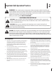
Important Safe Operation Practices 2 WARNING: This symbol points out important safety instructions which, if not followed, could endanger the personal safety and/or property of yourself and others. Read and follow all instructions in this manual before attempting to operate this machine. Failure to comply with these instructions may result in personal injury. When you see this symbol.
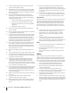
12. A missing or damaged discharge cover can cause blade contact or thrown object injuries. 13. Many injuries occur as a result of the mower being pulled over the foot during a fall caused by slipping or tripping. Do not hold on to the mower if you are falling; release the handle immediately. 14. a. Step back from mower to fully extend your arms. b. Be sure you are well balanced with sure footing. c. Pull the mower back slowly, no more than half way toward you. d. Repeat these steps as needed.
Service 3. Check the blade and engine mounting bolts at frequent intervals for proper tightness. Also, visually inspect blade for damage (e.g., bent, cracked, worn) Replace blade with the original equipment manufacture’s (O.E.M.) blade only, listed in this manual. “Use of parts which do not meet the original equipment specifications may lead to improper performance and compromise safety!” 4. Mower blades are sharp and can cut. Wrap the blade or wear gloves, and use extra caution when servicing them.
Notice Regarding Emissions Engines which are certified to comply with California and federal EPA emission regulations for SORE (Small Off Road Equipment) are certified to operate on regular unleaded gasoline, and may include the following emission control systems: Engine Modification (EM), Oxidizing Catalyst (OC), Secondary Air Injection (SAI) and Three Way Catalyst (TWC) if so equipped.
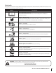
Safety Symbols This page depicts and describes safety symbols that may appear on this product. Read, understand, and follow all instructions on the machine before attempting to assemble and operate. Symbol Description READ THE OPERATOR’S MANUAL(S) Read, understand, and follow all instructions in the manual(s) before attempting to assemble and operate DANGER — ROTATING BLADES To reduce the risk of injury, keep hands and feet away.
Section 2 — Important Safe Operation Practices d line (repr esent s a 15 ° slop e) WARNING: Do not operate your lawn mower on such slopes. Do not mow on inclines with a slope in excess of 15 degrees (a rise of approximately 2-1/2 feet every 10 feet). A riding mower could overturn and cause serious injury. Operate riding mowers up and down slopes, never across the face of slopes. Operate walk-behind mowers across the face of slopes, never up and down slopes.
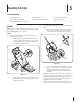
3 Assembly & Set-Up Contents of Carton • One Lawn Mower • One Grass Catcher • One Grass Catcher Adapter • One Side Discharge Chute • One Engine Operator’s Manual • One Bottle of Oil • One Lawn Mower Operator’s Manual Assembly 2. NOTE: This unit is shipped without gasoline or oil in the engine. Fill up gasoline and oil as instructed in the accompanying engine manual BEFORE operating your mower. Locate the hairpin clip on the weld pin on each side of lower handle. a. Handle 1.
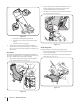
A 2. Replace with grass bag adapter, while making sure the front lip of adapter goes under the edge of the deck. Secure with wing nuts previously removed. 3. Lift chute door on the grass bag adapter and slide grass bag onto the adapter. See Fig. 3-5. B C 3 Figure 3-3 4. a. Hold blade control against upper handle. b. Pull starter rope out of the engine. Release blade control. c. Slip starter rope into rope guide. Attach cables to the lower handle with the cable ties already on the lower handle.
Adjustments Drive Control Cutting Height The adjustment wheel is located in the drive control handle housing and is used to tighten or loosen the drive belt. You will have to adjust the drive control if any of the following happens: The cutting height adjustment lever is located above the rear left wheel. See Fig. 3-7A insert. A 2 3 1 B The mower does not propel itself with the drive control engaged. 2. The mower’s drive wheels hesitate with the drive control engaged.
4 Controls and Features Blade Control Drive Control Electric Start Ignition Switch Shift Lever Cutting Height Adjustment Lever Recoil Starter Side Discharge Chute Figure 4-1 Blade Control The blade control is attached to the upper handle of the mower. Depress and squeeze it against the upper handle to operate the unit. Release it to stop engine and blade. WARNING: This blade control is a safety device. Never attempt to bypass its operations.
5 Operation Starting Engine 2 WARNING: Be sure no one other than the operator is standing near the lawn mower while starting engine or operating mower. Never run engine indoors or in enclosed, poorly ventilated areas. Engine exhaust contains carbon monoxide, an odorless and deadly gas. Keep hands, feet, hair and loose clothing away from any moving parts on engine and lawn mower. 3 3 3 Refer to engine manual for help with the engine. 1. Push primer (if equipped) three times.
6 Maintenance & Adjustments Maintenance 2. Lubricate the wheels and casters at least once a season with light oil (or motor oil). If wheels are removed for any reason, lubricate the axle bolt and inner surface of the wheel with light oil. See Fig. 6-1. General Recommendations • Always observe safety rules when performing any maintenance. 3. • The warranty on this lawn mower does not cover items that have been subjected to operator abuse or negligence.
Engine Care Adjustments A list of key engine maintenance jobs required for good performance by the mower is given below. Follow the accompanying engine manual for a detailed list and instructions. Shift Lever Cable • Maintain oil level as instructed in engine manual. • Service air cleaner every 25 hours under normal conditions. Clean every few hours under extremely dusty conditions. Poor engine performance and flooding usually indicates that the air cleaner should be serviced.
7 Service Blade Care WARNING: When removing the cutting blade for sharpening or replacement, protect your hands with a pair of heavy gloves or use a heavy rag to hold the blade. WARNING: An unbalanced blade will cause excessive vibration when rotating at high speeds. It may cause damage to mower and could break causing personal injury. 5. Lubricate the engine crankshaft and the inner surface of the blade adapter with light oil. Slide the blade adapter onto the engine crankshaft.
2. Remove the two screws securing battery cover to battery housing and place them to the side. See Fig. 7-2. 3. Open battery cover, remove positive and negative leads from battery, remove and replace with new battery. Connect the positive lead to the positive side of the battery pack, then connect the negative side. Charging Battery WARNING: The battery contains corrosive fluid and toxic material; handle with care and keep away from children.
Replacing Fuse Off-Season Storage The electric starter circuit and battery are protected by a 40 ampere fuse. If the fuse burns out, the electric starter will not operate. If the unit fails to start with the electric starter, perform the following steps to check the fuse inside the battery housing: The following steps should be taken to prepare your lawn mower for storage. • 1. Open the battery cover as described in Replacing Battery. See Fig. 7-2.
8 Troubleshooting Problem Engine Fails to start Cause Remedy 1. Blade control disengaged. 1. Engage blade control. 2. Spark plug boot disconnected. 2. Connect wire to spark boot. 3. Fuel tank empty or stale fuel. 3. Fill tank with clean, fresh gasoline. 4. Engine not primed (if equipped with primer). 4. Prime engine as instructed in the Operation section. 5. Faulty spark plug. 5. Clean, adjust gap, or replace. 6. Blocked fuel line. 6. Clean fuel line. 7. Engine flooded. 7.
Problem Uneven cut Mower will not self propel 20 Cause Remedy 1. Wheels not positioned correctly. 1. Place all four wheels in same height position (if equipped with individual height adjusters). 2. Dull blade. 2. Sharpen or replace blade. 1. Belt not installed properly. 1. Check belt for proper pulley installation and movement. 2. Debris clogging drive operation. 2. Stop engine, disconnect spark plug boot, and clean out debris. 3. Damaged or worn belt. 3. Inspect and replace belt.
Notes 9 21
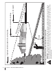
Model Series 990 4 1 5 69 70 2 71 68 6 3 50 5 10 9 8 12 45 7 15 5 13 40 52 17 65 61 59 23 47 21 14 46 23 18 22 25 51 26 27 20 72 28 29 37 30 23 19 41 57 58 44 51 56 55 54 39 53 42 36 38 35 43 31 32 33 22 62 63 60 22 24 48 66 64 16 49 73 11 34 67
Model Series 990 Ref No. Part Number Description Ref No. Part Number Description 38 710-0895 Screw, 1/4-15 x .750 Upper Control Housing† 39 664-0180 Grass Catcher Drive Control 40 747-0940A-0637 Support Rod w/ Rope Guide 753-0717 Lower Control Housing† 41 747-0939 Pivot Rod 5 710-1667A C Sunk Tap Screw, #10 x.
Model Series 990 12 14 13 6 20 21 47 22 27 44 23 34 37 1 2 32 59 29 30 36 26 28 45 42 55 31 56 41 7 6 18 38 23 9 11 13 39 43 48 23 17 55 46 52 49 51 12 8 54 5 3 4 33 50 57 24 16 30 10 14 48 53 35 40 23 25 24 58 56 19 15
Model Series 990 Ref No. 1 Ref No. Part Number Description Cotter Pin 29 682-7528-0637 Chain Cover Assembly Part Number 914-0474 Description 2 710-1652 Screw 1/4-14 x .825 30 741-0324A Flge Bearing .506 ID x .590 Lg 3 936-0264 Flat Washer.330 ID x.630 OD 31 682-7526-0637 Transmission Axle Assembly 4 914-0104 Cotter Pin 32 918-0263A Transmission Ass’y Complete 5 932-0306A Compression Spring 33 734-1857 Wheel 7 x 2 6 734-2010 Wheel, 9 x 2.
CUB CADET LLC MANUFACTURER’S LIMITED WARRANTY FOR walk-behind mowerS IMPORTANT: To obtain warranty coverage owner must present an original proof of purchase and applicable maintenance records to the servicing dealer. Please see the operator’s manual for information on required maintenance and service intervals.