Form No. 3357-361 Rev.
This Operator’s Manual is an important part of your snow thrower attachment. It will help you assemble, prepare and maintain the unit for best performance. Please read and understand what it says. TABLE OF CONTENTS 1. Rider Model Identification ................................ Page 3 2. Snow Thrower Attachment Safety ................... Page 4-5 3. Carton Contents .............................................. Page 6-7 4. Assembly Models 600-649 & 800 Series ........ Page 8-13 5.
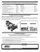
FastAttach™ Snow Thrower Attachment Model Plate .ccotsm 800-800-7310 w td p ro d u w w .m MTD LLC P. O. BOX 361131 44136 CLEVELAND,OH 330-220-4683 NOTE: This Operator’s Manual covers several models. Snow thrower hook-up instructions vary by model. Not all features discussed in this manual are applicable to all snow thrower attachments.
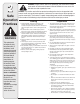
2 Safe Operation Practices WARNING This symbol points out important safety instructions which, if not followed, could endanger the personal safety and/or property of yourself and others. Read and follow all instructions in this manual before attempting to operate this machine. Failure to comply with these instructions may result in personal injury. When you see this symbol.
Operation Maintenance & Storage 1. Do not put hands or feet near rotating parts, in the auger/impeller housing or chute assembly. Contact with the rotating parts can amputate hands and feet. 2. The auger/impeller control lever is a safety device. Never bypass its operation. Doing so makes the machine unsafe and may cause personal injury. 3. The control levers must operate easily in both directions and automatically return to the disengaged position when released. 4.
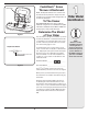
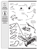
3 Carton Contents Self-Adhesive Reflectors Extension Spring Idler Assembly Belt Keeper & Hardware Extension Spring Idler Pulley & Pin Wing Nut Belt Keeper & Hardware Cable Ties Clamp If you are missing any parts, please do not contact the retailer where you purchased this unit, call MTD directly at 1-330-220-4MTD or toll free at 1-800-800-7310.
CONTENTS OF CARTON Before beginning installation, remove all parts from the carton to make sure everything is present. Carton contents are listed below and shown in Figure 3. Hardware part numbers are shown in parentheses.
4 Assembly Model Series 600-649 & All 800 series. WARNING Before installing attachment, place tractor on a firm and level surface. Place the PTO in the disengaged (OFF) position, set the parking brake, shut engine off and remove key to prevent unintended starting. WARNING: Before installing attachment, place tractor on a firm and level surface. Place the PTO in the disengaged (OFF) position, set the parking brake, shut engine off and remove key to prevent unintended starting.
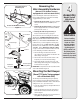
Reversing the Idler Assembly Hardware Flange Nut, Washer & Shoulder Spacer (Manual PTO Garden Tractors equipped with a 46-inch deck ONLY) If you’re mounting this snow thrower attachment to a tractor equipped with any deck other than a manually engaged 46-inch, proceed to either: 1. Mounting the Idler Assembly (for tractors equipped with a 42, 46, 50 & 54-inch deck ONLY) in this section Double-idler Bracket/Front Pulley Figure 5 3-in. Hex Bolt Undercarriage Spacers 3.
4 Assembly Model Series 600-649 & All 800 series Cub Cadet 11C & 13C Mounting the Idler Assembly Before installing attachment, place tractor on a firm and level surface. Place the PTO in the disengaged (OFF) position, set the parking brake, shut engine off and remove key to prevent unintended starting.
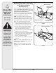
Belt Keeper Pin Flange Lock Nut & Washer PTO Cable Slotted Fitting Idler Pulley & Idler Bracket Figure 10a Undercarriage Assembly 1. Remove the v-belt (754-0371A), this belt will be replaced later with another v-belt (754-0498) included in this carton. Also, remove all of the Clevis Pins and Click pins as seen in Figure 10b. 2. Remove the flange lock nut and washer as pointed out in Figure 10a, leaving the spacer underneath it in place.
4 Assembly Model Series 600-649 & All 800 series Because this snow thrower attachment is compatible with several model lawn tractors and garden tractors with either an electric PTO or a manual PTO, four upper drive belts are included. If you have had any problems locating the proper upper belts for installation in the previous steps, use the table below for quick reference.
4. Align the holes in the rear of the lift arms with the holes in the rear of the undercarriage and insert the clevis pins removed in step 1. Fasten with the hairpin clips. See Figure 14. Lift Arm 5. Move the tractor’s deck lift lever into the top notch on the right fender allowing the lift arms and the rear of the undercarriage assembly to rise. 6.
5 Bracket & Undercarriage Assembly Model Series 700-799 Bracket Assembly Wiring Harness Clamp WARNING: Before installing attachment, place tractor on a firm and level surface. Place the PTO in the disengaged (OFF) position, set the parking brake, shut engine off and remove key to prevent unintended starting. NOTE: Left side view NOTE: Your tractor’s cutting deck, PTO belt and front deck stabilizer bracket must be removed prior to mounting the snow thrower attachment.
Spindle Pulley Belt Keeper Pin 6. Install the additional belt keeper pin and hardware included with the loose parts in this carton. See Figure 19 for belt keeper location placement. Mounting the Undercarriage Assembly Make certain the correct upper drive belt (754-0498) is installed on the undercarriage assembly. If the appropriate belt is not installed, replace it with the correct belt prior to proceeding with mounting the undercarriage.
6 Assembling Controls Upper Chute Crank Rod Joint Block Lower Chute Crank Rod B All Models A Chute Directional Control Assembly NOTE: All references to left or right side of the snow thrower is from the operating position only. Figure 24 Attaching the Chute Directional Control Attaching The Lift Handle 1. Secure the upper chute crank rod to the joint block (A) on the lower chute crank rod with the cotter pin (B) provided. See Figure 24. 1.
7 Inset A Mounting Auger Housing All Models WARNING Inset B Figure 27 Mounting Auger Assembly 4. Maneuver the auger housing until the mounting holes lineup. Insert a clevis pin from your hardware pack 1. Position the auger housing assembly in front of the tractor and secure with a click pin, into the tractor’s front pivot as seen in Figure 27. Lay the belt and support tubes out as support brackets seen in Figure 27 Inset B. seen above. 5.
8 Routing the Upper Drive Belt (Tractors Models with an Electric PTO) Spindle Pulley Engine Pulley Idler Pulley Belt Routing Various Models All electric PTO Decks 42, 46, 50, 54 PTO Idler Pulley Figure 29 1. Attach and route the upper drive belt around the spindle pulley and idler pulley found on the undercarriage, the electric PTO clutch and the PTO idler pulley as illustrated in Figure 29.
8 Routing the Upper Drive Belt (Older Style Tractors ) 46 inch Manual Older Style Setup 42 in. Electric and Manual Older Style Setup Figure 31 1. Attach and route the proper upper drive belt (refer to the table on page 12) around the spindle pulley and idler pulley found on the undercarriage, the lower portion of the engine pulley and the two pulleys found on the PTO double-idler bracket as illustrated in Figure 31.
9 Controls WARNING: Be familiar with all controls and their proper operation. Know how to stop the machine and disengage them quickly. Engaging the Augers and Impeller Power to the snow thrower attachment is activated by engaging the tractor’s PTO. 1. Place the tractor’s throttle control in the FAST (rabbit) position and allow it to remain there for efficient snow removal. WARNING Be familiar with all controls and their proper operation. Know how to stop the machine and disengage them quickly. 2.
OPERATION a foreign object, move the PTO into the disengaged (OFF) position immediately and turn off the tractor’s engine and remove the ignition key. Examine the auger area thoroughly for damage and do NOT operate the snow thrower attachment until any damage is repaired. WARNING: Read, understand, and follow all instructions and warnings on the tractor, attachment, and in the Operator’s Manuals before operating.
11 Adjustments All Models Making Adjustments WARNING: Never attempt to make any adjustments while the engine is running, except where specified in the Operator’s Manual. Place tractor on a firm and level surface. Place the PTO in the disengaged (OFF) position, set the parking brake, shut engine off, and remove key to prevent unintended starting.
Maintenance Lube Spiral and Chute Base WARNING: Before lubricating, repairing, or inspecting, place tractor on a firm and level surface. Place the PTO in the disengaged (OFF) position, set the parking brake, shut engine off, and remove key to prevent unintended starting. Lubrication of Chute Directional Control Joint Block Auger Shaft 1. At least once a season, remove the shear bolts on the auger shaft.
�� �� �� �� �� �� �� �� �� �� �� �� �� �� �� �� � �� �� �� �� �� �� �� �� �� �� � � � �� � �� � �� � �� �� �� �� �� � �� � �� �� �� �� �� �� �� �� � � �� �� �� �� � � �� �� �� �� �� �� �� �� �� �� �� �� �� �� �� �� 24 � �� �� �� �� ��
REF NO. PART NUMBER DESCRIPTION Qty REF NO. PART NUMBER DESCRIPTION Qty. 1 Auger Gear Box (Incl. Ref. 23-41) 1 34 Grease Seal 1 2 Impeller Assembly, 12” 1 35 Flat Washer, .76 x 1.5 x .030 2 3 Housing Assembly 1 36 Flat Washer, .508 x 1.0 x .020 4 4 Housing Brace Bracket 1 37 Thrust Washer, .75 x 1.25 x .0615 2 5 LH Spiral Auger 3 38 Thrust Bearing, .75 x 1.25 x .078 1 6 RH Spiral Auger 3 39 Flange Bearing, .503 x .75 1 7 Hex Cap Screw, 5/16-24 x .
52 55 20 56 16 19 60 18 17 62 57 58 56 15 61 54 1 4 14 29 26 22 2 8 59 50 21 4 51 42 28 3 22 48 9 39 24 12 4 4 10 4 38 43 47 7 11 35 33 5 B 53 33 6 13 36 65 40 32 B 32 C 34 39 31 45 46 30 C 25 49 64 4 A 65 63 4 69 71 23 29 70 4 41 72 A 67 68 66 44 73 4 67 65 37 26 27
REF NO. PART No. DESCRIPTION Qty. REF NO. PART No. DESCRIPTION Qty. 1 Knob 1 38 Flat Washer, .51 x 1.0 x .060 4 2 Chute Tilt Handle 1 39 Flat Washer, .64 x 1.12 x .125 4 3 Chute Tilt Cable Guide 1 40 Bell Washer, .396 x 1.14 x .095 2 4 Nylon Hex Lock Nut, 5/16-18 22 41 Drive Mounting Bracket 1 5 Chute Tilt Bracket Assembly 1 42 Shoulder Screw, .5 x .29, 3/8-16 2 6 Carriage Bolt, 5/16-18 x 1.5 2 43 Flange Bearing w/ Flats 2 7 Saddle Washer, .32 x .
AA 38 AA 1 42 54 51 44 39 6 59 9 10 41 57 50 10 8 46 40 64 10 8 58 7 12 16 48 12 39 38 6 18 8 43 49 10 45 BB 47 34 13 2 A 33 9 31 35 37 16 4 11 14 56 18 3 52 61 BB 25 36 29 30 60 10 53 25 62 28 55 3 26 A 20 12 25 5 27 10 16 19 15 17 22 21 23 24 63 28
13 REF NO. PART No. DESCRIPTION Qty. REF NO. PART No. DESCRIPTION Qty. 1 Spindle Assembly (Incl. 38-44) 1 33 Hex Nut, 3/8-24 1 2 Pulley Mounting Bracket 1 34 Extension Spring, .620 x 5.62 1 3 Hex Cap Screw, 3/8-16 x 1.75 2 35 Lock Washer, 3/8 1 4 Self Tapping Screw 4 36 Idler pulley, 4” Diameter 1 5 Clevis Pin, .5 x 1.18 2 37 Idler Pivot Arm 1 6 Belt Keeper Pin † 4 38 Flange Nut 5/8-18 2 7 Clevis Pin, 3/8 x .
14 NOTES: Use this page to make notes and write down important information.
14 NOTES: Use this page to make notes and write down important information.
MANUFACTURER’S LIMITED WARRANTY FOR The limited warranty set forth below is given by MTD LLC with respect to new merchandise purchased and used in the United States, its possessions and territories. “MTD” warrants this product against defects in material and workmanship for a period of two (2) years commencing on the date of original purchase and will, at its option, repair or replace, free of charge, any part found to be defective in materials or workmanship.