Hydrostatic Zero-Turn Commercial Riding Mower Professional Turf Equipment 48” Fabricated Deck 54” Fabricated Deck 60” Fabricated Deck 72” Fabricated Deck OPERATOR’S AND SERVICE MANUAL
TABLE OF CONTENTS Foreword. . . . . . . . . . . . . . . . . . . . . . . . . . . . . . . . . . . . . . . . . . . . . . . . . . . . . . . . . . . . . . . 3 General Safety Operations . . . . . . . . . . . . . . . . . . . . . . . . . . . . . . . . . . . . . . . . . . . . . . . . . 4 A.Danger . . . . . . . . . . . . . . . . . . . . . . . . . . . . . . . . . . . . . . . . . . . . . . . . . . . . . . . . . . 4 B. Warning . . . . . . . . . . . . . . . . . . . . . . . . . . . . . . . . . . . . . . . . . . . . . . .
FORWARD The Tank Hydrostatic Zero-Turn Commercial Riding Mower provides superb maneuverability, mid-mount cutting capability for professional landscapers, commercial lawn service companies, professional turf managers and golf course superintendents. The machine incorporates many safety features that should be studied by all operators and maintenance personnel before use. The list of safety precautions should receive particular attention.
GENERAL SAFETY OPERATIONS 6. Do not check for hydraulic leaks with any part of the body. 7. Do not add fuel to a machine when the engine is running and/or the exhaust system is hot. 8. Keep machine clean and free of debris, grass, leaves, oil, grease, etc. 9. Place lap bars in neutral/start position, set park brake, disengage P.T.O., turn engine off, and remove ignition key before you dismount from machine. 10. Use machines laterally or diagonally across slopes, avoid going downhill when possible. 11.
should be avoided. Loose connections at the battery terminals can produce sprks and heat...connections to the terminals must be kept tight, and the terminals and battery surfaces kept clean of acids and corrosion. If batteries are re-charged or “jumped” from external sources, make sure that the connections are made properly and in the correct sequence...connect to the positive terminal of the good battery first, then connect that to the positive terminal of the weak battery.
13. 14. 15. 16. tion switch. Inspect for damage. Repair any damage. Make sure the blades are in good condition and that the blade bolts are tight before restarting the engine. Never leave the mower unattended without: turning off the blade clutch switch; placing the left and right steering levers in the neutral position; moving the throttle to slow; setting the parking brake; shutting off the engine and taking the key from the ignition switch.
8. 9. 10. 11. 12. the ROPS could come in contact with any structures, trees, etc. The ROPS and seat belt add additional mass that elevates the machine’s Center of Gravity (C.G.) which negatively affects the machine’s stability and traction....use extra caution when operating on slopes. Inspect the ROPS and seat belt assemblies on a regular basis for damage and improper operation....replace all components that are damaged or are not functioning properly with authorized replacement parts.
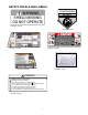
SAFETY DECALS AND LABELS WARNING SHIELD MISSING DO NOT OPERATE TO REDUCE THE RISK OF INJURY, D O N OT O P E RAT E M OW E R U NL E S S DISCHARGE CHUTE COVERORGRASS C A T C H E R IS I N I T S P R O P E R P L A C E . D AN GER K E E P H A N D S a n d FE E T A W A Y Part Number: 00030635 Part Number: 01002166 Part Number: 777S32801 Part Number: 777S33014 Part Number: 777S32797 Part Number: 02005110 ! WARNING! Maximum weight on hitch is 50 lbs. Maximum towed load is 500 lbs.
SPECIFICATIONS GENERAL INFO. Controls: Parking Brake: Seat: Frame: Instrumentation Front Caster Wheels: Drive Wheels: Tire Pressure: Fuel Tank: Ground Speed: Net Weight: ENGINE INFO. Engine: Type: Air Cleaner: Lube System: Hydraulic System: Starter: Blade Brake Clutch: Engine ignition and start switch; throttle; choke; left and right steering levers; electric blade clutch switch; parking brake; mower deck lift Mechanical linkage brake handle to internal drum brakes Adjustable seat and armrests.
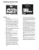
OPERATING INSTRUCTIONS Figure. 1 Engine throttle Choke Lever Figure. 2 Ignition Switch Electric Blade Clutch Switch Tach and Hour Meter Parking Brake A.General k. 1. When Mowing: a. Keep adults, children, and pets away from the area to be mowed. b. When operating this mower, in the forward direction, do not allow the steering levers to return to Neutral on their own.
grease, grass, and leaves to reduce the chance of fire and permit proper cooling. Note: If low traction conditions occur, follow these procedures for “zero turns”: To turn clockwise (front of machine moves toward RIGHT) when traveling FORWARD: 1. Come to a stop, 2. Then slowly move both lap bars rearward (no more than 1/2 maximum reverse speed) to initiate REVERSE travel, 3. Then slowly move the LEFT lap bar forward while maintaining the RIGHT lap bar in the rearward travel position. 4.
Steering Levers Note: The 19hp and 23hp use the 5 gallon fuel tank. Figure. 4 Foot Pedal Lift Figure. 3 wheel, making the mower turn toward the side where the lever is behind. When one lever is pushed forward and the other lever pulled back the same amount, one traction wheel will turn in reverse and the mower will turn within its own length. In order to start the engine, both steering levers must be in the neutral position; the parking brake must be engaged; and the blade clutch switch must be “off”.
direction until it stops, it will shut off the flow of fuel to the engine. When turned in a counterclockwise direction it will open and allow fuel to flow to the engine. Close this valve if you are not going to run the mower for a period of 30 minutes or more to prevent flooding the engine. 8. Seat Adjustment Lever: The Seat Adjustment Lever is located beneath the seat. The Seat Adjustment Lever is used to move the seat forward and backward.
(See Figure 5). You may also need to adjust the Deck Links (See Figure 5). c. Become familiar with all of the machine controls, instrumentation, safety and instruction signs, and safety devices. d. Move (or have moved) the machine to a safe, level area with no obstructions including objects, pedestrians, and animals. 2. Initial Operation: a. Use protective equipment for eyes, hands, hearing, feet, legs, head and other areas of the body if needed — safety eye glasses, gloves, earplugs, boots, hats, etc.
utes. Be sure to totally retard the choke after the engine has “warmed up”. g. Check safety devices: 1. With the park brake engaged, try to move one of the lap bars (speed/directional control) from the neutral/start position — the lap bars should not move with the park brake engaged. 2. Repeat this procedure with the opposite side lap bars. 3.
f. Insert the key in the ignition and start switch and turn the switch to “On”. g. Gasoline Engine: If the engine is cold, push the choke to the on position. j. Note: E.F.I. Tanks do not have a choke control. k. h. Turn the ignition key in a clockwise direction to the “Start” position until the engine starts. Note: Do not hold the key in the “Start” position for more than 10 seconds or you may damage the starter. If the engine does not start in this time, wait about 30 seconds and try again. i.
lengths of grasses are removed, and grass conditions are generally dry. l. MAINTENANCE AND SERVICE Clean up the grass clippings and other materials washed from underneath the mower deck, and dispose of them properly. Hose Coupler (Shown without Hose Attached) WARNING: Water Port Disconnect the spark plug wires or remove the key from the ignition to prevent the engine from accidentally starting before performing any maintenance on this mower. A. Cleaning your Deck Figure.
Height of Cut Clevis Pin Main Frame Linch Pins Figure. 7 Linch Pins conventional electric grinder or a hand file to sharpen the blades. d. Replace any blade with severe nicks or dents that cannot be removed by filing. e. Check the balance of the blade after sharpening by placing it on a blade balancer. Do not use un-balanced blades. f. If the blade dips on one end, file stock off of the cutting surface on that end. 2. Changing a Blade: a. Remove the Key from the ignition and disconnect the spark plug.
Cover Plate Spindle Figure. 9 1. Hydraulic Tank Adding Hydraulic Oil (use Rimula SAE15W40) Place the Mower on a level surface and engage the parking brake. b. Stop the engine and remove the key from the ignition switch. c. Clean the area around the Hydraulic Oil fill neck. d. Remove the hydraulic fill cap and check the level. The correct level is a 1/4” below the oil tank fill neck. e. Pour hydraulic oil into the reservoir a 1/4” below the oil tank fill neck, if necessary. a. Figure.
caps and drain oil from both left and right pumps. Replace and retighten nuts. c. Store the battery with a full charge. A discharged battery will freeze (refer to the table below). Hydraulic pumps Figure. 10 Unfasten hose and drain from this side of both pumps. j. Remove the three screws from the top of the oil filter and replace the oil filter element. Coat the sealing surface with Shell Rimula 15W40 oil or equivalent. Install the three screws back into the oil filter. k.
engine does not start, engage the parking brake and start the engine. c. Seat Switch: With both steering levers in the neutral position, the parking brake engaged and the blade clutch switch in the “off” position, start the engine. Now release the parking brake, hold down on the back of the operator’s seat against spring pressure. Release the operator’s seat and the engine should stop. If the engine does not stop, the seat switch must be replaced.
2. Leaking Tires: When a flat tire occurs, repair or replace immediately. The normal procedure is to remove the wheel and replace it with a spare. Take the leaking tire to a maintenance area and repair. If a tire is getting soft, park the mower on the nearest level, paved area. If the leaking tire is on a traction wheel, put blocks on each side of the opposite traction wheel and jack up the tire that leaks about an inch off the ground. Loosen and remove the lug nuts and remove the wheel.
2. hoses. Make certain there are no kinks or twists in any hose. Hydraulic Oil Tank and Filter: uum causing violent bubbling in the hydraulic oil in the pump. Check the two suction hoses (the hoses connected to the filter) daily before starting the engine. Look for a flattened condition or any leaks and repair or replace as necessary. A flattened or leakng suction hose will permit cavitation to develop which can destroy the pumps in a short time.
ing holes in each lap bar whenever the lap bars are in their Neutral positions. perature. Before storing, the following maintenance procedures should be performed. Note: Both lap bars must be in their Neutral Note: For E.F.I. Tanks, disconnect the negative lead of the battery for storage of 4 weeks or more.
MAINTENANCE SCHEDULE 7. D. Every 100 Hour Checks A. Daily Checks 1. 1. Before starting engine: a. Check the fuel level.** b. Check the engine oil level.** c. Check the hydraulic oil level. d. Check the hydraulic hoses for leaks, abrasion, kinks, twists, or a flattened condition. e. Check the tires and tire pressure. Drive Tires: 8-10 psi. Front Caster Wheels: 20-25 psi. f. Check the spindle belt, the mower drive belt and the hydro drive belt. g. Check the blades.
. OIL CHART Apply a few drops of engine oil or use a spray lubricant. Apply the oil to both sides of pivot points. Wipe off any excess. Start engine and operate mower briefly to insure that oil spreads evenly.
Performance Adjustments B. Engine RPM Check and Adjustment A. High Speed Tracking Adjustment If mower tracks to one side with both lap bars in fully forward position: 1. 2. 3. 4. 5. 6. High RPM Spec. Low RPM Spec. 23, 31 & 37Hp Kawasaki 3600 +/-50 1550 +/-100 27 & 30HP Kohler 3600 +/-50 1550 +/-100 NOTE: RPM Specs. are for free running engines under no load. Check air pressure in all four tires: a. Pressure should be within specified ranges and balanced side-to-side. b. Rear tires 8-10 psi.
g. Verify proper throttle adjustment by checking RPM readings as outlined above. b. 4. C. Deck Corner Ball Wheel Roller Settings Note: If lap bar adjustments are required, 1. Matching the set heights of the ball rollers on the four corners of the mower deck to the desired cut height will prevent edge scalping and minimize any side-to-side variance in cut height. 2. There are three height adjustment holes in the bracket that mount the ball rollers to the deck. a.
F. Deck leveling Procedure 1. 2. 3. 4. 5. 6. 7. aligned along the mower centerline. The bladeto-ground height at the rear of the blade tip should be 1/8" to 1/4” higher than the front tip. This is referred to as blade pitch. The sam height difference should be true for the left blade, measured front and back. 8. To adjust the blade pitch the deck pitch must be adjusted. Loosen the inner jam nuts at the rear of the horizontal threaded rods.
WIRING DIAGRAM GD: 02002824 30
Abraisive (sandy), dry Material Collection Mulch Low cut height (1" to 2") Very lush &/or tall grass Stems (Dandelion, Bahia, Buckhorn, etc.
SLOPE GAUGE TTE A1 5 ° S LOP E OR A FENCE POST A CORNER OF A BUILDING A POWER POLE SIGHT AND HOLD THIS LEVEL WITH A VERTICAL TREE USE THIS PAGE AS A GUIDE TO DETERMINE SLOPES WHERE YOU MAY NOT OPERATE SAFELY. FO L D O N DO D LI N E , REP RE S E NTIN G 15° WARNING Do not mow on inclines with a slope in excess of 15 degrees (a rise of approximately 2-1/2 feet every 10 feet). A riding mower could overturn and cause serious injury.
This Page Intentionally Left Blank 33
This Page Intentionally Left Blank 34
MANUFACTURER’S LIMITED WARRANTY FOR CUB CADET COMMERCIAL TANK ZERO-TURN COMMERCIAL RIDING MOWER IMPORTANT: To obtain warranty coverage owner may be required present proof of purchase and applicable maintenance records to the servicing dealer. Please see the operator’s manual for information on required maintenance and service intervals. In addition, Cub Cadet may deny warranty coverage if the hour meter, or any part thereof, is altered, modified, disconnected or otherwise tampered with.