Operator’s Manual 60" Mid Mount Mower Deck Model 59A40009727 Cub Cadet Yanmar LLC P.O. Box 361052 Cleveland, Ohio 44136-1052 PRINTED IN U.S.A.
Table of contents Important Safe Operation Practices ................................................................................................................ 2 To the Dealer and Owner ................................................................................................................................ 4 Safety Labels . ................................................................................................................................................. 5 Contents ................
SLOPE OPERATION 5. Never allow children under 14 years old to operate the machine. Children 14 years and older should only operate the machine under close parental supervision and proper instruction. 6. Use extra care when approaching blind corners, shrubs, trees or other objects that may obscure your vision of a child or other hazard. 7. Remove the key when the machine is left unattended to prevent unauthorized operation. 1.
12. If the machine should begin to vibrate abnormally, stop the engine and check immediately for the cause. Abnormal vibration is a warning of trouble. 13. Observe proper disposal laws and regulations. Improper disposal of fluids and materials can harm the environment and the ecology. a. Prior to disposal, contact your local Environmental Protection Agency to determine the proper method for disposing of the waste.
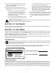
• KEEP HANDS AND FEET AWAY FROM ROTATING PARTS. • REMOVE OBJECTS THAT CAN BE THROWN BY THE BLADE IN ANY DIRECTION. WEAR SAFETY GLASSES. • DO NOT MOW WHEN CHILDREN OR OTHERS ARE AROUND. NEVER CARRY CHILDREN EVEN WITH BLADES OFF. • USE EXTRA CAUTION ON SLOPES. DO NOT MOW SLOPES GREATER THAN 15°. MOW UP AND DOWN, NOT ACROSS. AVOID SUDDEN TURNS, USE LOW SPEED. S30503 ASSEMBLE CHUTE DEFLECTOR TO THIS UNIT BEFORE OPERATING. WARNING SHIELD MISSING DO NOT OPERATE. READ OPERATOR'S MANUAL.
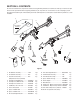
SECTION 5: CONTENTS The mower deck attachment components are listed below along with their part numbers. Assemblies are made up of more than one part and do not have a part number. Before beginning installation, lay all components out on a flat surface to assure everything is present. Throughout the manual the parts in the hardware pack will be identified by name, followed by their callout number in parenthesis, to aid in installation.
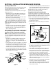
Section 6: Installation MOWING and Removal Unpacking the Mower Deck • insert the hex screw through the ball joint and fasten with the hex lock nut (20). Tighten the hex lock nut until almost snug against the ball joint. Do not overtighten. Refer to Figure 2. Repeat the above procedure to install the other rear lift rod assembly on the other subframe assembly. Move the tractor and mower deck to a firm flat area large enough to accommodate both.
Preparing the tractor • WARNING!: Engage the tractor parking brake, stop the tractor engine and remove the key to safely install the mower deck. • Installing Subframe and Lift Bracket Assemblies NOTE: The RH and LH subframe assemblies can be installed without removing the rear wheels. But limited space to remove and reinstall fasteners makes it more difficult and increases the possibility of an improper installation.
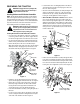
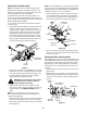
• • • Place a 4.95" long spacer (15) between the rear subframe mtg./link pin support bracket and the transmission housing, and align with the holes in both as shown in Figure 6. Insert the long hex screw removed earlier through the bracket and spacer and thread into the transmission housing, but do not fully tighten. Working from the rear of the tractor, slide the RH lower hitch link pin almost fully to the left.
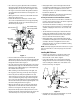
Attaching Rear Lift Rod Assembly NOTE: If a lift rod assembly is too short to align the ball joint and lift bracket holes, refer to “Adjusting the Rear Lift Rod Assemblies” below and turn the rod as shown in Figure 11 to lengthen the rod assembly as needed to connect to the lift bracket. NOTE: The forward end of the rear lift rod assemblies should already have been attached to the subframe lift arms.
• Use a 9/16" open end wrench on the flats of the lift rod to turn the lift rod in the direction shown in Figure 11 to shorten the lift rod assembly. • While observing the position of the rear lift arm in the lockout bracket, continue to turn the lift rod until the rear lift arm almost contacts the upper surface of the lockout bracket (Refer to Figure 9). When the lift rod is properly adjusted, tighten the jam nut against the ball joint. Refer to Figure 11.
• Move to the other side of the tractor and repeat the above procedure to capture the deck hitch bracket pin in the rear lift link on the other side of the tractor. Refer to Figure 13. • From either side of the tractor, remove internal cotter pin and withdraw the clevis pin from the front lift link on the deck. Refer to Figure 14. • • Align the locking collar of the drive shaft with the mid - PTO shaft and slide the drive shaft fully onto the PTO shaft.
Using Subframe Lock out WARNING!: Never position any part of your body beneath tractor implements held in the raised position only by the tractor’s hydraulic system. A sudden loss of pressure could cause the implement to fall and could result in severe injury. Removal of the mower deck is not necessary to utilize implements attached to the 3 - point hitch. The subframe lock feature allows the 3 - point hitch links to be raised and lowered without also raising and lowering the mower deck.
Section 7: Adjustments Adjusting Deck gauge wheels Adjusting the Rear Gauge Wheels The 60" mower deck is equipped with ground following front caster wheels and is designed to be operated with the front caster wheels and rear gauge wheels on the ground. Consequently, the adjusted position of the front caster wheels and rear gauge wheels determine the cutting height. There are six cutting height positions ranging from 1-1/4" to 5".
LEVELING THE MOWER DECK • Although the mower deck is designed to operate with the front caster wheels and rear gauge wheels on the ground, some mowing conditions may require the mower deck to be operated with the deck wheels off the ground. To assure a quality cut in those situations, the deck should be properly leveled. Correct adjustment of the mower deck will level the deck from side to side, and provide the correct front to back pitch of the mower deck.
• • Carefully turn the outer blades of the mower deck so that the ends of the blades point to the front and rear of the deck. See Figure 21. • On each side of the tractor, use a 9/16" wrench on the flats of each rod to turn the rod. Turn each rod as shown in Figure 22 to shorten the rod and raise the front of the deck, or to lengthen the rod and lower the front of the deck. Adjust both front lift rods in small increments, while continuing to re-measure the front and rear blade heights.
Section 8: deck Maintenance Blade care Nozzle Adapter WARNING!: Stop the tractor engine, disengage all PTO controls, engage the parking brake, and wait for all movement to stop before adjusting the deck wheels. Adapter Lock Collar Pull Lock Collar Back The cutting blades must be kept sharp at all times.
• Clean away any grass clippings and debris that may have collected around spindle pulleys and belt. • The deck gear box is lubricated and sealed, and does not require additional lubrication. • Align the LH belt cover tabs with the slots in the index bracket and push the cover outward so that the tabs are fully engaged in the slots and the cover holes align with the speed nuts on the cover brackets. Install the two hex screws and fully tighten.
spindle belt replacement • A worn spindle belt will affect the quality of cut from the mower deck and should be replaced. Referring to Figure 23, replace the spindle belt as follows: Install New Spindle Belt • Remove Spindle Belt • • • • Remove the two hex screws securing the LH belt cover to the deck. Slide the belt cover tabs from the slots of the deck index bracket to remove the cover. Refer to Figure 20 Remove the three hex cap screws securing the RH belt cover and remove the belt cover.
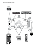
Section 9: deck & subframe parts list Subframe 21 20 9 33 30 1 38 43 11 24 31 28 41 34 27 34 37 19 32 44 41 38 12 8 41 38 25 3 42 38 33 13 35 36 25 31 30 41 22 2 26 40 4 7 26 47 45 45 39 17 16 23 5 6 46 15 28 29 10 14 20 18 21
Subframe Ref. Part No. Number Description Qty. Ref. Part No. Number Description Qty. 1 603-04420 Shaft, Deck Subframe 2 25 710-3144 Screw, Hex Cap, 3/8-16 x 2.0 Gr5 4 2 603-04421 Arm, Front Lift RH 1 26 711-04845 Pin, .625 Dia.
Mower Deck 918-3129C 22
Mower Deck Ref. Part No. Number Description Qty. Ref. Part No. Number Description Qty. 1 603-04413 Bracket, Deck Wheel 2 42 714-0115 Pin, Cotter, 1/8 x 1.0 1 2 603-04416 Deck Housing 1 43 714-0117 Pin, Internal Cotter 2 3 603-04418 Handle, Wheel Height Adjustment 1 44 714-0128 Key, Square, 1/4 x 1.