Hydrostatic Zero-Turn Commercial Riding Mower Professional Turf Equipment 60” Fabricated Deck Digital Fuel Injection, Liquid Cooled OPERATOR’S AND SERVICE MANUAL
TABLE OF CONTENTS Foreword. . . . . . . . . . . . . . . . . . . . . . . . . . . . . . . . . . . . . . . . . . . . . . . . . . . . . . . . . . . . . . . 3 General Safety Operations . . . . . . . . . . . . . . . . . . . . . . . . . . . . . . . . . . . . . . . . . . . . . . . . . 4 A.Danger . . . . . . . . . . . . . . . . . . . . . . . . . . . . . . . . . . . . . . . . . . . . . . . . . . . . . . . . . . 4 B. Warning . . . . . . . . . . . . . . . . . . . . . . . . . . . . . . . . . . . . . . . . . . . . . . .
FORWARD The Tank Hydrostatic Zero-Turn Commercial Riding Mower provides superb maneuverability, mid-mount cutting capability for professional landscapers, commercial lawn service companies, professional turf managers and golf course superintendents. The machine incorporates many safety features that should be studied by all operators and maintenance personnel before use. The list of safety precautions should receive particular attention.
GENERAL SAFETY OPERATIONS 5. Keep all safety signs legible and properly installed. 6. Do not check for hydraulic leaks with any part of the body. 7. Do not add fuel to a machine when the engine is running and/or the exhaust system is hot. 8. Keep machine clean and free of debris, grass, leaves, oil, grease, etc. 9. Place lap bars in neutral/start position, set park brake, disengage P.T.O., turn engine off, and remove ignition key before you dismount from machine. 10.
terminals can produce sprks and heat...connections to the terminals must be kept tight, and the terminals and battery surfaces kept clean of acids and corrosion. If batteries are re-charged or “jumped” from external sources, make sure that the connections are made properly and in the correct sequence...connect to the positive terminal of the good battery first, then connect that to the positive terminal of the weak battery.
13. 14. 15. 16. damage. Make sure the blades are in good condition and that the blade bolts are tight before restarting the engine. Never leave the mower unattended without: turning off the blade clutch switch; placing the left and right steering levers in the neutral position; moving the throttle to slow; setting the parking brake; shutting off the engine and taking the key from the ignition switch. Never walk or stand on the discharge side of a mower with the engine running.
8. 9. 10. 11. 12. over....use caution in (or avoid) areas where the ROPS could come in contact with any structures, trees, etc. The ROPS and seat belt add additional mass that elevates the machine’s Center of Gravity (C.G.) which negatively affects the machine’s stability and traction....use extra caution when operating on slopes. Inspect the ROPS and seat belt assemblies on a regular basis for damage and improper operation....
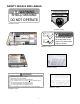
SAFETY DECALS AND LABELS WARNING SHIELD MISSING DO NOT OPERATE TO REDUCE THE RISK OF INJURY, D O N OT O P E RAT E M OW E R U NL E S S DISCHARGE CHUTE COVERORGRASS C A T C H E R IS I N I T S P R O P E R P L A C E . D AN GER K E E P H A N D S a n d FE E T A W A Y Part Number: 00030635 Part Number: 01002166 DANGER ROTATING BLADE Do not put hands or feet under or into mower when engine is running.
SPECIFICATIONS GENERAL INFO. Controls: Seat: Frame: Instrumentation: Front Caster Wheels: Drive Wheels: Tire Pressure: Fuel Tank: Ground Speed: Net Weight: Engine ignition and start switch; throttle; left and right steering levers; electric blade clutch switch; parking brake; mower deck lift Mechanical linkage attached to the brake handle and drum brakes Adjustable seat with armrests.
OPERATING INSTRUCTIONS Figure. 1 Hour Meter (tach optional) indicator lights Figure. 2 Electric Blade Clutch Switch Ignition Switch Engine throttle Parking Brake A.General maintain the uphill side lap bar “essentially” in a fixed position. k. Be careful when crossing gravel paths or roadways. Always turn off the blade clutch switch and wait until the blades stop rotating and raise the cutting deck to the transport position. Always allow other vehicles to have the right of way. l.
of grease, grass, and leaves to reduce the chance of fire and permit proper cooling. Note: If low traction conditions occur, follow these procedures for “zero turns”: To turn clockwise (front of machine moves toward RIGHT) when traveling FORWARD: 1. Come to a stop, 2. Then slowly move both lap bars rearward (no more than 1/2 maximum reverse speed) to initiate REVERSE travel, 3. Then slowly move the LEFT lap bar forward while maintaining the RIGHT lap bar in the rearward travel position. 4.
Steering Levers Figure. 3 Foot Pedal Lift from the rear to the front will increase the engine speed from slow to fast. 3. Left and Right Steering Levers: (See Figure 3.) These hinged levers open out to the side in any position to permit the operator to be seated or to leave the mower’s seat. The operator, when seated, can pull the levers up to the operating position, a comfortable forearm’s length away. These levers control all of the movements of the mower.
fuel tank (beside the engine on the left or right side of the mower). When the fuel reaches one inch from the top of the tank, stop. DO NOT OVERFILL. Space must be left for expansion. b. Engine Oil: (Filled at the factory before shipment.) Pull out the oil dipstick, wipe it off and reinsert it. Pull it out again and read the oil level. If it is below the operating range, add oil through the fill tube using a funnel to bring it up to the top of the operating range. Figure.
b. lower the mowing deck into the cutting position. Using a ruler, pencil and paper, measure and note the distance from the paved surface to the bottom edge of the mowing blade at the front and the back of the deck on each side of the mower. (Four dimensions.) Note: The front edge of the mowing deck should be 1/8"-1/4" below the rear edge of the deck so that the blades are cutting grass in only the front half of their circular path. This decreases friction and reduces the drive power required. c.
e. This is a one person machine, operator only! Riders are not permitted under any circumstance! f. To start the engine on the machine: 1. Make sure the park brake is set to the “ON” position, both lap bars are in the neutral/ start position, and the Power Take Off (PTO also referred to as blade control switch) is in the “off” (down) position. 2. Move the engine speed control (throttle) forward (half way). 3.
moving the LEFT lap bar rearward. Release both lap bars and the machine should stop turning (this is a safety check, the normal procedure is for the operator to slowly bring the lap bars to the neutral position). 3. Start the Engine: a. Open the fuel shutoff valve by selecting the left or right tank position. b. Sit on the Seat. Set the parking brake “On”. c. Make sure that the left and right steering levers are in their neutral position. d. Turn the electric blade clutch switch “Off”. e.
Height of Cut Clevis Pin Main Frame Figure. 6 Linch Pins Linch Pins levels. Bahia blades are configured without offset, and with a maximum amount of sharpened cutting edge. c. Remove tension of the PTO belt by moving the belt tensioning rod. Note: There is a certain amount of spring tension due to the weight of the deck. When removing the lift linkage from the deck the tension of the springs will go from the deck to the lift handle.
b. Unscrew the wing nuts from the deck covers and remove both covers. c. Using a 1/2" socket breaker bar or socket rachet insert the male end into the 1/2" opening in the lower idler arm assembly and pull the idler arm clockwise. While holding the idler arm back, loosen the blade drive belt from the pulley and slide the belt away from the pulley. d. Remove tension of the PTO belt by moving the belt tensioning rod. Loosen the belt retaining bolt. e.
caps and drain oil from both left and right pumps. Replace and retighten nuts. Hydraulic pumps Figure. 8 Hydraulic Tank Figure. 9 1. Adding Hydraulic Oil (use Rimula SAE15W40) Place the Mower on a level surface and engage the parking brake. b. Stop the engine and remove the key from the ignition switch. c. Clean the area around the Hydraulic Oil fill neck. d. Remove the hydraulic fill cap and check the level. The correct level is a 1/4” below the oil tank fill neck. e.
b. Clean the battery before storing. A dirty battery will lose its charge over time. c. Store the battery with a full charge. A discharged battery will freeze (refer to the table below). Specific Gravity Freezing Temp (°F) 1.265 -71 1.250 -62 1.200 -16 1.150 5 1.100 16 d. Recharge battery when ever the specific gravity value is less than 1.225 3. Battery Removal Warning: When removing the cables from the battery follow these steps to avoid a short between the wrench and the frame. a. b. c. d.
start. If it does, the parking brake switch must be repositioned or perhaps replaced. If the engine does not start, engage the parking brake and start the engine. c. Seat Switch: With both steering levers in the neutral position, the parking brake engaged and the blade clutch switch in the “off” position, start the engine. Now release the parking brake, hold down on the back of the operator’s seat against spring pressure. Release the operator’s seat and the engine should stop.
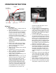
mower is parked with the engine shut off, the hydraulic system locks the traction wheels. 2. Note: To move the mower forward or in reverse by pushing, you must release the dynamic braking. Locate the valves on the pump. Turn valves counter-clockwise (using a standard 7/16” wrench) one quarter turn to push the unit. After pushing the mower to the desired location, return both valves to the operating position by turning the valve clockwise, but do not overtighten (See photo below). Bypass Valve hoses.
violent bubbling in the hydraulic oil in the pump. whenever the lap bars are in their Neutral positions. Check the two suction hoses (the hoses connected to the filter) daily before starting the engine. Look for a flattened condition or any leaks and repair or replace as necessary. A flattened or leakng suction hose will permit cavitation to develop which can destroy the pumps in a short time.
in temperature. Before storing, the following maintenance procedures should be performed. e. Push the mower outdoors and start the engine. Let the engine idle until it has warmed up completely (4 to 5 minutes). a. Clean the mower. The entire tractor and cutting deck should be washed and cleaned. b. Sharpen the blades so that the mower will be ready to use when needed. c. Protect the metal surfaces. Repair scratches with the appropriate touch-up spray paint.
MAINTENANCE SCHEDULE 7. D. Every 100 Hour Checks A. Daily Checks 1. 1. Before starting engine: a. Check the fuel level.** b. Check the engine oil level.** c. Check the hydraulic oil level. d. Check the hydraulic hoses for leaks, abrasion, kinks, twists, or a flattened condition. e. Check the tires and tire pressure. Drive Tires: 8-10 psi. Front Caster Wheels: 20-25 psi. f. Check the spindle belt, the mower drive belt and the hydro drive belt. g. Check the blades.
. OIL CHART Apply a few drops of engine oil or use a spray lubricant. Apply the oil to both sides of pivot points. Wipe off any excess. Start engine and operate mower briefly to insure that oil spreads evenly.
Performance Adjustments B. Enginge RPM Check and Adjustment A. High Speed Tracking Adjustment If mower tracks to one side with both lap bars in fully forward position: 1. 2. 3. 4. 5. 6. High RPM Spec. Low RPM Spec. 29 Hp Kawasaki 3700 +/-50 1550 +/-100 NOTE: RPM Specs. are for free running engines under no load. 1. Check air pressure in all four tires: a. Pressure should be within specified ranges and balanced side-to-side. b. Rear tires 8-10 psi. recommended (20 psi MAX.) c.
C. Deck Corner Ball Wheel Roller Settings 3. 1. Matching the set heights of the ball rollers on the four corners of the mower deck to the desired cut height will prevent edge scalping and minimize any side-to-side variance in cut height. 2. There are three height adjustment holes in the bracket that mount the ball rollers to the deck. a. Use the top set of holes for cut heights of 2 inches or lower. b. c.
F. Deck leveling Procedure 1. 2. 3. 4. 5. 6. 7. mower centerline. The blade-to-ground height at the rear of the blade tip should be 1/8" to 1/4” higher than the front tip. This is referred to as blade pitch. The sam height difference should be true for the left blade, measured front and back. 8. To adjust the blade pitch the deck pitch must be adjusted. Loosen the inner jam nuts at the rear of the horizontal threaded rods.
WIRING DIAGRAM GD: 02002951 30
MANUFACTURER’S LIMITED WARRANTY FOR CUB CADET COMMERCIAL TANK ZERO-TURN COMMERCIAL RIDING MOWER IMPORTANT: To obtain warranty coverage owner may be required present proof of purchase and applicable maintenance records to the servicing dealer. Please see the operator’s manual for information on required maintenance and service intervals. In addition, Cub Cadet may deny warranty coverage if the hour meter, or any part thereof, is altered, modified, disconnected or otherwise tampered with.