Hydrostatic Zero-Turn Commercial Riding Mower Professional Turf Equipment 72" Fabricated Deck ILLUSTRATED PARTS LIST 1
TABLE OF CONTENTS Frame Assembly . . . . . . . . . . . . . . . . . . . . . . . . . . . . . . . . . . . . . . .3 72" Fabricated Cutter Deck . . . . . . . . . . . . . . . . . . . . . . . . . .4 and 5 72" Spindle Assembly . . . . . . . . . . . . . . . . . . . . . . . . . . . . . .6 and 7 Hydro Hose and Pump Assembly . . . . . . . . . . . . . . . . . . . . 8 and 9 Brake Assembly . . . . . . . . . . . . . . . . . . . . . . . . . . . . . . . . .10 and 11 Fuel Tank Assembly . . . . . . . . . . . . . . . . . . . .
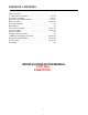
Frame Assembly- Figure 1 and Parts List GD: 02003025-10/16/06 Ref. No. 1 2 3 4 5 6 7 8 9 10 11 12 13 14 15 16 17 18 19 20 21 Part No. 00002528 00012152 00022560 01000372 01000643 01001170 01001776 01002511 01003282 01003993 01005160 01007779 01008225 01010119 02002655 02003055 02003074 02003501 02003505 02003541 02003563 Description Hex Cap Screw 3/8-16 x 2.00 Lock Nut w/Nylon Insert Hex Nut, 3/8-16 Flange Lock Carriage Bolt, 3/8-16 x .75 Long Carriage Bolt, 3/8-16 x 1 Rubber Bumper, .62 OD x .
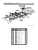
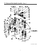
72" Fabricated Cutter Deck - Figure 2 GD: 02002933-10/26/06 4
72" Fabricated Cutter Deck - Parts List for Figure 2 Ref. No. Part No.
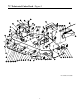
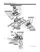
72" Fabricated Deck Spindle Assembly - Figure 3 GD: 02003628-10/30/06 6
2" Fabricated Deck Spindle Assembly - Parts List for Figure 3 Ref. No. 1 2 3 4 5 6 7 8 9 10 11 12 13 14 15 16 17 18 19 20 21 22 23 24 25 26 27 28 29 30 31 32 33 34 35 36 37 38 39 40 41 42 43 44 Part No.
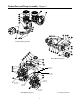
Hydro Hose and Pump Assembly - Figure 4 Pump & Motor Systems Motor Mount Systems 3/4" Hose 11.0" LG. 3/4" Hose 12.0" LG. 3/4" Hose 12.0" LG. 3/4" Hose 16.0" LG. 3/4" Hose 12.0" LG. 3/4" Hose 16.0" LG.
Hydro Hose and Pump Assembly- Parts List for Figure 4 Ref. No. 1 2 3 4 5 6 7 8 9 10 11 12 13 14 15 16 17 18 Part No. Description 00012157 Washer lock 3/8 zinc 00012428 Washer lock 3/8 zinc 00020628 Key, 3/16" x 7/8" 00022560 Flange Lock Hex Nut, 3/8-16 00030261 Cap, Hydro Oil Tank 00034167 Hex Cap Screw 3/8-16 x 5.00 01000369 Hex Cap Screw, 3/8 -16 x 1.25 01000372 Carriage Bolt, 3/8-16 x .75 LG. 01000642 Carriage Bolt, 3/8-16 x 5.50 01000643 Carriage Bolt, 3/8-16 x 1 01002010 Carriage Screw, 3/8-16 x 1.
Brake Assembly - Figure 5 GD: 02002926-01/03/07 10
Brake Assembly - Parts List for Figure 5 Ref. No. Part No. 1 00010958 2 00011447 3 00011450 4 00014608 5 00022560 6 00030906 7 01000372 8 01000443 9 01000628 10 01000930 11 01002766 12 01008198 13 01008225 14 01008531 15 01008539 16 02000362 17 02002797 18 02002796 19 02002823 20 02002889 21 02002864 22 02002874 23 02002971 24 02002972 25 02003010 26 02003603 27 02003725 28 02003770 29 02003774 30 02003776 31 02003782 32 02003841 Description Washer, 1/2 Zinc Hex Cap Screw, 1/4-20, 1.
Fuel Tank Assembly - Figure 6 and Parts List GD: 02001910-12/13/06 Ref. No. 1 2 3 4 5 6 7 8 9 Part No. 02003809 00012470 01000723 01000368 00012157 02003842 01000600 01007425 02001908 -00012235 01003473 10 02002253 11 01000215 12 02003573 Description Fuel Cap, 3.5 Cable Tie Flat Washer, .406 ID, 1.0 OD, .105 Hex, Cap Screw, 3/8-16, .88 Lock Washer, 3/8 Fuel Tank Flat Washer, 1.4 x .630 x .
Rear Bumper - Figure 7 and Parts List GD: 02003564-10/25/06 Ref. No. 1 2 3 4 5 6 7 Part No. 00012428 00022560 00030046 01009992 02002536 02003570 02003634 Description Hex Nut, 1/2-13, Insert Lock Nut, Hex 3/8-16 Flange Lock HHCS, 1/2-13, 3.00 Bar, Weight Hitch Bracket Carriage Bolt, 3/8-16 x 3.00 Rear Bumper 13 Qty.
Front Caster Assembly - Figure 8 GD: 02002925-10/04/06 14
Front Caster Assembly - Parts List for Figure 8 Ref. No. 1 2 3 4 5 6 7 8 9 10 11 12 13 14 15 16 17 18 19 20 21 22 Part No. 00012577 00023287 00060078 01000678 01002620 01002621 01002622 01002624 01002626 01002627 01003123 01006294 01006309 01006347 01006912 01006961 01007407 01007760 01009997 02000588 02000589 02002821 02002108 02002106 02002107 Description Washer, 1/2 x 1 Shim Nut, 1/2-20, Center Lock Grease Fitting Nut, Jam, 1.
Control Assembly- Figure 9 GD: 02002550-01/03/07 16
Control Assembly - Parts List for Figure 9 Ref. No. Part No. 1 00002528 2 00012186 3 00013131 4 00013198 5 00013416 6 00021958 7 00022560 8 00061053 9 01000371 10 01000372 11 01000450 12 01000451 13 01000600 14 01000628 15 01000635 16 01000960 17 01001170 18 01002511 19 01002766 20 01002986 21 01003561 22 01003947 23 01004003 24 01004129 25 01005851 26 01006350 27 01007312 Description Hex Cap Screw, 3/8-16 x 2.00 Hex Nut, 1/4-20 Hex Cap Screw, 1/4-20, .75 Hex Cap Screw, 5/16-18 x 2.00 HHCS, 1/4-20 x 1.
Wheel Assembly - Figure 10 and Parts List 2 1 GD: 02002669-10/04/06 Ref. Qty. No. Part No. Description 1 00012187 Lug Nut, 1/2-20 8 2 02002668 Wheel Assembly, 24 x 12.00-12, Beige Includes: 2 00073975 Tire, 24 x 12.00-12, Turf Master Rim, 12 Dia x 8.50 width OPTIONAL TIRES 01002182 Wheel Assembly, 24 x 12.00-12, Turf Saver 01004473 Tire, 24 x 12.
Seat/Floor Panel Assembly- Figure 11 and Parts List GD: 02002559-12/19/06 Ref. No. Part No. 1 00002528 2 00006131 3 00012158 4 00012165 5 00012168 6 00012178 7 00012428 8 00013131 9 00021956 10 00022560 11 01000226 12 01000372 13 01000523 14 01000628 15 01000873 Description Hex Cap Screw 3/8-16 x 2.00 Hex Nut, 3/8-16 Washer Nylock Nut, 5/16-18 Lock Washer, 5/16 Hex Cap Screw, 5/16-18 x 1/2 Nut, 1/2-13, Nylon Insert Screw, Hex, Cap, 1/4-20 x .
37HP Kawasaki Engine Assembly - Figure 12 Description Air Filter Air Filter (Inner) Fuel Filter Oil Filter Spark Plug Part Number GD: 02003537-09/26/06 20
37HP Kawasaki Engine Assembly - Parts List for Figure 12 Ref No 1 2 3 4 5 6 7 8 9 10 11 12 13 14 15 16 17 18 19 20 21 22 Part No. Description 00005763 Hex Nut, 7/16-14 00010980 Hex Head Cap Screw, 3/8-16 x 1.50 00012157 Washer lock 3/8 zinc 00014602 Round Hd. Machine Screw, 10-32 x 3/4 00014608 Lock Nut, Nylon Insert, 10-32 00022560 Flange Lock, Hex Nut, 3/8-16 00060056 Nut Washer, W/Star, 8-32 00060078 Grease Fitting, 1/4-28 x 3/16 01000302 Shoulder Screw, 7/16-14 01000364 Hex Carriage Screw, 3/8-16, 1.
Electrical Assembly Kawasaki - Figure 13 Fasten relay (01002251) with self-tapping screw (01000628) on LH control panel shown in Fig. 11.
Electrical Assembly Kawasaki - Parts List for Figure 13 Ref. No. 1 2 3 4 5 6 7 8 9 10 11 12 13 14 15 16 17 18 19 20 21 22 23 24 25 26 27 Part No. 00012032 00012470 00013131 00013258 00014602 00014608 00022560 00032097 01000372 01001811 01002111 01002251 01002766 01003581 01004040 01004078 01005389 01009905 02000024 02002059 02002552 02002592 02002822 02002824 02003775 02003038 723-3064 Description Battery, 12V 225CCA 30 Min Tie, Cable, 3/16 x .05 x 7.4" Screw, Hex, Cap, 1/4-20 x .
Lift Assembly - Figure 14 GD: 02003030-10/31/06 24
Lift Assembly - Parts List for Figure 14 Ref. No. 1 2 3 4 5 6 7 8 9 10 11 12 13 14 15 16 17 18 19 20 21 22 23 24 25 26 27 28 29 30 31 32 33 34 35 36 37 38 39 40 41 42 43 44 45 46 47 48 49 50 51 52 Part No.
Decal Map 01002166 777D10677 01007756 On top of front rail on main frame (Beside S/N Label) 777D10679 Near deck wash out 02003753 777D10677 00030635 Top of deck under belt cover 02003514 02003616 Aligned near fuse mounting holes on inner side control panel 01006087 777S32801 777D09015 777D10679 Near deck wash out 00030633 02003753 Centered on rear bumper 02003676 On bottom of Foot Platform 02002693 Centered top of Tow Hitch 777S32797 777D09752 Both sides of unit 02002041 On top of Hydraul
This Page Intentionally Left Blank 27
Cub Cadet Commercial P.O. Box 368023 Cleveland, OH 44136 Form No. 02003431 Rev.