Hydrostatic Zero-Turn Riding Mower MODEL 23HP 53AB5BBP750 50" Stamped Deck ILLUSTRATED PARTS LIST
This Page Left Blank Intentionally 2
TABLE OF CONTENTS 50" Formed Cutter Deck . . . . . . . . . . . . . . . . . . . . . . . 4 and 5 Hydro Pump Assembly . . . . . . . . . . . . . . . . . . . . . . . . 6 and 7 Brake Assembly . . . . . . . . . . . . . . . . . . . . . . . . . . . . . 8 and 9 Fuel Tank Assembly . . . . . . . . . . . . . . . . . . . . . . . . . . . . . . 10 Rear Bumper . . . . . . . . . . . . . . . . . . . . . . . . . . . . . . . . . . . 11 Front Caster Assembly . . . . . . . . . . . . . . . . . . . . . . . . . . . .
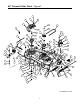
50" Formed Cutter Deck - Figure 1 5 51 37 37 48 3 55 9 47 18 59 31 59 61 33 53 46 36 34 62 50 29 28 24 38 21 13 6 15 58 11 27 22 33 64 6 62 35 14 1 19 4 17 10 19 65 6 32 67 49 30 44 68 19 39 56 57 25 2 66 54 20 43 6 6 12 14 69 63 16 7 6 8 62 17 12 70 40 60 41 6 23 52 12 26 42 45 GD: 02000420-12/14/04 4
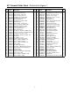
0" Formed Cutter Deck - Parts List for Figure 1 Ref. No. 1 2 3 4 5 6 7 8 9 10 11 12 13 14 15 16 17 18 19 20 21 22 23 24 25 26 27 28 29 30 31 32 33 34 35 Part No. 00003107 00008495 00012226 00012470 00013406 00022560 00027279 00034167 01005011 00060078 01009635 01000372 01000375 01000385 01000387 01000393 01000628 01000635 01000723 01001169 01001745 01002010 01002564 01003123 01003245 01003253 01004081 01004101 01004118 01004751 01005201 01006181 01006535 01006680 01008456 Ref. Description Qty. No.
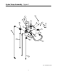
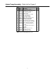
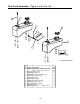
Hydro Pump Assembly - Figure 2 1 5 3 10 6 7 8 17 19 18 15 9 8 4 16 14 11 13 12 GD: 01004266-03/29/01 6
Hydro Pump Assembly - Parts List for Figure 2 Ref. No. 1 2 3 4 5 6 7 8 9 10 11 12 13 14 Part No. 00006144 00012529 00013131 00017665 01004166 00022560 00030261 00031994 01000372 01004516 01001650 01004192 01004267 01004268 01004269 15 01004270 16 17 18 19 01004272 01006959 01004702 01006353 Description Hex Cap Screw, 3/8-16, 1 Protective Hose Cover (not shown) Hex Cap Screw, 1/4-20, .
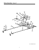
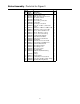
Brake Assembly - Figure 3 25 21 3 13 16 12 14 30 19 9 29 15 26 23 11 18 7 22 20 24 10 4 5 6 17 27 1 2 8 28 GD: 01001609-04/21/03 8
Brake Assembly - Parts List for Figure 3 Ref. No. 1 2 3 4 5 6 7 8 9 Part No. 00006131 00009678 00011888 00021955 00021956 00012226 01000100 00022560 01000628 10 11 12 13 14 15 16 17 18 19 20 21 22 23 24 25 26 01000723 01000872 01002751 01002771 01002772 01002980 01003591 01003410 01003593 01008886 01003417 01003595 01003574 01003575 01003576 01003716 01003730 27 28 29 30 01004265 01002511 00012173 01006350 01008889 Description Qty.
Fuel Tank Assembly - Figure 4 and Parts List 8 9 3 4 10 13 11 12 7 2 1 6 5 GD: 01002568-01/18/01 Ref. No. 1 2 3 4 5 6 7 8 9 10 11 12 13 Part No. 01000723 -00012235 01000069 01000368 00012157 01004350 01003116 01000281 01003473 00031081 00012470 01000600 Description Flat Washer, .406 ID, 1.0 OD, .105 Hose, 1/4" Fuel Line (in inches) Clamp, Union Fuel Cap, 3.5 Hex, Cap Screw, 3/8-16, .
Rear Bumper - Figure 5 and Parts List 3 5 1 4 6 2 GD: 01007365-04/08/04 Ref. No. 1 2 3 4 5 6 Part No. 00012428 00022560 00030046 01000364 01007362 01009992 Description Hex Nut, 1/2-13, Insert Lock Nut, Hex 3/8-16 Flange Lock HHCS, 1/2-13, 3.00 Carriage Bolt, 3/8-16 x 1.75 Rear Bumper Bracket Bar Weight 11 Qty.
Front Caster Assembly - Figure 6 and Parts List 1 15 3 5 13 12 2 14 7 7 6 Washer Order and Orientation 11 4 13 8 6 Front Plate 17 9 02000588 10 01006294 16 Front Axle 01006294 Frame 02000588 01009997 GD: 02000572-10/21/04 Ref. No. 1 2 3 4 5 6 7 8 9 10 11 12 13 14 15 16 17 Part No. 00006144 01000872 00012157 00023287 00023793 02000588 00060078 01000678 01002611 01004128 01007364 02000570 01006294 01006309 02000589 01006559 01009997 Description Qty.
Wheel Assembly - Figure 7 and Parts List 2 1 GD: 01006503-06/09/04 Ref. No. Part No. Description 1 00012187 Lug Nut, 1/2-20 2 01006541 Wheel Assembly, 23 x9.5-12, Dr, White: Includes Tire, Turf Saver, 23 x 9.50-12, 2-Ply Rim, 12 Dia x 7.00 width, 4x4 Bolt 13 Qty.
Control Assembly- Figure 8 45 43 31 6 38 41 36 29 37 49 27 56 19 52 14 2 40 11 13 33 58 50 46 39 11 12 7 3 16 47 44 55 1 17 10 51 11 42 1 53 48 35 32 21 28 30 3 18 20 34 25 1 5 10 22 12 10 4 25 7 8 23 24 25 15 9 10 46 6 53 26 GD: 02000569-01/12/05 14
Control Assembly - Parts List for Figure 8 Ref. No. Part No. 1 2 3 4 5 6 7 8 9 10 11 12 13 14 15 16 17 18 19 20 21 22 23 24 25 26 00003107 00011861 00022560 00060078 00013131 01000369 01000372 00012152 01000450 01000451 01000628 01000635 00013406 01000960 01002990 01000308 01001727 01003044 01004265 01003045 01004265 01002511 01002980 01002982 01002983 01002984 01002986 01002987 01002988 Description Qty . Cotter Pin .125 Dia x 1.0 6 Hex Cap Screw, 3/8-16, 2.
Drive Assembly- Figure 9 and Parts List 29 2 22 21 11 4 7 19 23 1 5 14 3 12 5 20 10 17 8 24 25 27 15 18 26 28 6 27 16 3 9 13 8 GD: 01002578-01/12/05 Ref. No. 1 2 3 4 5 6 7 8 9 10 11 12 13 14 15 Part No. 00002528 00011459 00011861 00012157 00012169 00013198 00022560 01000372 750-3119 01000635 01000643 01000723 01001623 01001975 01001618 Description Hex Cap Screw, 3/8-16 x 2 Flat Washer, 1/2 Hex Cap Screw, 3/8-16 x 2.
Seat Assembly- Figure 10 and Parts List 7 6 3 5 2 1 8 4 GD: 01007314-01/10/05 Ref. No. 1 2 3 4 5 6 7 8 Part No. 00022560 01000635 01001630 01002634 01002753 750-3119 01006545 01000960 Description Nut, Hex 3/8-16 Flange Lock Lock Nut, Hex Flange, 5/16-18 Mounting Bracket, Seat Shoulder Screw, .50x2.345, 3/8-16 Grommet, 2.5 OD x 1.0 Long Spacer, .406 ID x 1.00 OD x .38 Adjustable Seat, Black Flat Washer, .406 ID, 1.00 OD, .105 17 Qty.
23HP Kohler Engine Assembly - Figure 11 4 16 34 35 36 30 11 7 26 19 8 10 1 17 13 5 32 33 22 37 24 7 25 29 27 2 6 20 3 12 23 28 31 13 14 15 21 9 Description Air Filter Pre Filter Fuel Filter Oil Filter Spark Plug Gasket Exhaust (2) 18 Part Number KH-24-083-03-S KH-24-083-05-S KH-24-050-10-S KH-12-050-08 759-3336 -- GD: 02000424-01/04/05 18
23HP Kohler Engine Assembly - Parts List for Figure 11 Ref No Part No. Description Qty. 1 00005763 Hex Nut, 7/16-14 1 2 00006129 HHCS, 5/16-18, 1-3/4 4 3 01007533 Key, 1/4 x 1/4 x 2.75 1 4 00012169 Flat Washer, 5/16 2 5 00014602 Round Hd.
18HP Electrical Engine Assembly - Figure 12 and Parts List 15 1 10 4 5 2 11 7 23 13 20 22 7 19 18 6 16 9 12 14 17 3 GD: 02000573-10/22/04 Ref. No. 1 2 3 4 5 6 7 8 9 Part No. 00012032 00012289 00012470 00013131 00013258 00032097 01000628 Description Battery Cable, Battery, Red, 36" Tie, Cable, 3/16 x .05 x 7.4" Screw, Hex, Cap, 1/4-20 x .75 Boot, 1" OD Rubber Battery-PST, Red Nut, W/Cap, 5/8-32 Ignition Screw, TT, 1/4-20 x .
Floor Panel Assembly- Figure 13 and Parts List 2 5 12 4 6 8 13 9 1 7 3 10 11 GD: 02000360-10/21/04 Ref. No. 1 2 3 4 5 6 7 8 9 10 11 12 13 Part No. 00012132 00012158 00013131 00014608 00021956 00030906 00083192 01001170 01001638 01004992 02000361 02000362 02000433 Description Qty. Lock Washer, 1/4 2 Washer AR Hex Cap Screw, 1/4-20, .75 2 Lock Nut, Nylon Insert, 10-32 3 Hair Pin, 3/8-1/2 2 Screw, Phillips Head, Machine, 10-32 x 5/8 3 Washer 2 Rubber Bumper, .62 OD x .
Lift Assembly - Figure 14 9 6 17 8 18 45 11 24 12 42 22 19 7 21 21 41 27 22 43 31 32 11 20 27 14 15 9 44 22 22 5 14 45 45 28 25 45 40 16 2 18 27 45 7 36 30 4 32 16 29 45 27 On units with the Foot Pedal Deck Lift this washer (01003123) is removed. 37 35 39 34 23 13 32 3 10 26 33 38 GD: 01007373-11/22/04 1 OPTIONAL FOOT PEDAL DECK LIFT 5 2 Ref. No. 1 2 3 4 5 6 7 8 9 10 11 12 3 Part No.
Lift Assembly - Parts List for Figure 14 Ref. No. 1 2 3 4 5 6 7 8 9 10 11 12 13 14 15 16 17 18 19 20 21 22 23 24 25 26 27 28 29 30 31 32 33 34 35 36 37 38 39 40 Part No.
Assembly Pump Right Hand- Figure 15 and Parts List 7 1 Set Screw Position 2 3 5 4 6 8 Ref. No. 1 2 3 4 5 6 7 8 9 Part No. 01000635 01001807 01001808 01001809 01001995 01007264 01004296 01000548 01004161 Description Hex Flange, Lock Nut, 5/16-18 Gear, Spur, 14T O-Ring, 2.00 x .070 Parking Brake Lever Pin, Spirol, 3/16 x 1.25 HD Transmission Assembly Pump Rib Neck Stud, 1/2-20 Set Screw, 5/16 - 24 x 1.25 24 Qty.
Assembly Pump Left Hand- Figure 16 and Parts List 7 8 3 2 6 1 5 Set Screw Position 4 GD: 01007266-07/03/01 Ref. No. 1 2 3 4 5 6 7 8 9 Part No. 01000635 01001807 01001808 01001809 01001995 01001545 01007264 01000548 01004161 Description Lock Nut, Hex Flange 5/16-18 Gear, Spur, 14T O-Ring, 2.00 x .070 Parking Brake Lever Pin, Spirol, 3/16 x 1.25 HD Pump Transmission Assembly Rib Neck Stud, 1/2-20 Set Screw, 5/16 - 24 x 1.25 25 Qty.
Frame Assembly- Figure 17 and Parts List 1 3 2 6 4 5 GD: 01007401-12/02/04 Ref. No. 1 2 3 4 5 6 Part No. 00022560 01000372 01001713 01001617 02000129 01008225 Description Hex Nut, 3/8-16 Flange Lock Carriage Bolt, 3/8-16 x .75 Long Bracket Assembly, Frame, Front Frame Assembly Cover, Hydro Fan Push Retainer, 3/8" 26 Qty.
Notes 27
Cub Cadet Commercial P.O. Box 368023 Cleveland, OH 44136 Form No. 02000705 Rev.