Safe Operation Practices • Set-Up • Operation • Maintenance • Service • Troubleshooting • Warranty Operator’s Manual Two-Stage Snow Thrower — 526 WE WARNING READ AND FOLLOW ALL SAFETY RULES AND INSTRUCTIONS IN THIS MANUAL BEFORE ATTEMPTING TO OPERATE THIS MACHINE. FAILURE TO COMPLY WITH THESE INSTRUCTIONS MAY RESULT IN PERSONAL INJURY. CUB CADET LLC, P.O. BOX 361131 CLEVELAND, OHIO 44136-0019 Printed In USA Form No.
1 To The Owner Thank You Thank you for purchasing a Snow Thrower manufactured by Cub Cadet LLC. It was carefully engineered to provide excellent performance when properly operated and maintained. Please read this entire manual prior to operating the equipment. It instructs you how to safely and easily set up, operate and maintain your machine. Please be sure that you, and any other persons who will operate the machine, carefully follow the recommended safety practices at all times.
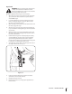
Important Safe Operation Practices 2 WARNING! This symbol points out important safety instructions which, if not followed, could endanger the personal safety and/or property of yourself and others. Read and follow all instructions in this manual before attempting to operate this machine. Failure to comply with these instructions may result in personal injury. When you see this symbol.
Safe Handling of Gasoline 5. To avoid personal injury or property damage use extreme care in handling gasoline. Gasoline is extremely flammable and the vapors are explosive. Serious personal injury can occur when gasoline is spilled on yourself or your clothes which can ignite. Wash your skin and change clothes immediately. Never run an engine indoors or in a poorly ventilated area. Engine exhaust contains carbon monoxide, an odorless and deadly gas. 6.
Maintenance & Storage Do not modify engine 1. Never tamper with safety devices. Check their proper operation regularly. Refer to the maintenance and adjustment sections of this manual. 2. Before cleaning, repairing, or inspecting machine disengage all control levers and stop the engine. Wait until the auger/impeller come to a complete stop. Disconnect the spark plug wire and ground against the engine to prevent unintended starting. To avoid serious injury or death, do not modify engine in any way.
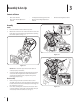
3 Assembly & Set-Up Contents of Carton • One Snow Thrower • Two Replacement Auger Shear Pins • One Snow Thrower Operator’s Manual • One Tecumseh Engine Operator’s Manual • One Product Registration Card Assembly Handle 1. Place the shift lever in the Forward-6 position 2. Observe the lower rear area of the snow thrower to be sure both cables are aligned with roller guides before pivoting the handle upward. See Fig. 3-1.
3. Finish securing chute control assembly to chute support bracket with wing nut and hex screw removed earlier. See See Fig. 3-4. Set-Up Shear Pins A pair of replacement auger shear pins and bow tie cotter pins are included with your snow thrower. Store them in your snow thrower’s dash panel until needed. See Fig. 3-6. Figure 3-4 4. Check that all cables are properly routed through the cable guide on top of the engine. See Fig. 3-5.
Tire Pressure Adjustments Before operating, check tire pressure and reduce pressure in both tires to between 15 psi and 20 psi. Skid Shoes NOTE: If the tire pressure is not equal in both tires, the machine may not travel in a straight path and the shave plate may wear unevenly. The snow thrower skid shoes are adjusted upward at the factory for shipping purposes. Adjust them downward, if desired, prior to operating the snow thrower.
Auger Control Warning! Prior to operating your snow thrower, carefully read and follow all instructions below. Perform all adjustments to verify your snow thrower is operating safely and properly. Check the adjustment of the auger control as follows: 1. When the auger control is released and in the disengaged “up” position, the cable should have very little slack. It should NOT be tight. 2. In a well-ventilated area, start the snow thrower engine. Refer to Starting the Engine on page 12.
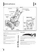
4 Controls and Features Figure 4-1 Snow thrower controls and features are described below and illustrated in Fig. 4-1. Choke Control NOTE: For detailed information on all engine controls, refer to the separate Tecumseh Engine Operator’s Manual. Shift Lever The shift lever is located in the right side of the handle panel and is used to determine ground speed and direction of travel. Forward There are six forward (F) speeds. Position one (1) is the slowest and position six (6) is the fastest.
Throttle Control Auger Control The throttle control is located on the rear of the engine. It regulates the speed of the engine and will shut off the engine when moved into the STOP position. Primer Pressing the primer forces fuel directly into the engine’s carburetor to aid in cold-weather starting. Oil Fill Engine oil level can be checked and oil added through the oil fill. Skid Shoes Position the skid shoes based on surface conditions. Adjust upward for hard-packed snow.
Chute Directional Control Chute Clean-Out Tool Warning! Never use your hands to clear a clogged chute assembly. Shut off engine and remain behind handles until all moving parts have stopped before unclogging. The chute clean-out tool is conveniently fastened to the rear of the auger housing with a mounting clip.
5 Operation Starting The Engine 1. 2. 3. Attach spark plug wire to spark plug. Make certain the metal loop on the end of the spark plug wire (inside the rubber boot) is fastened securely over the metal tip on the spark plug. 6. Recoil Starter 1. Make certain both the auger control and drive control are in the disengaged (released) position. Move throttle control up to FAST position. Insert ignition key into slot. Make sure it snaps into place. Do not attempt to turn the key. 2.
To Engage Drive 1. With the throttle control in the Fast (rabbit) position, move shift lever into one of the six forward (F) positions or two reverse (R) positions. Select a speed appropriate for the snow conditions and a pace you’re comfortable with. 2. Squeeze the drive control against the handle the snow thrower will move. Release it and drive motion will stop. To Engage Augers 1. To engage the augers and start throwing snow, squeeze the auger control against the left handle.
6 Maintenance & Adjustments Maintenance Lubrication Engine Gear Shaft Refer to the Tecumseh Engine manual packed with your machine for all engine maintenance. The gear (hex) shaft should be lubricated at least once a season or after every twenty-five (25) hours of operation. Shave Plate and Skid Shoes 1. The shave plate and skid shoes on the bottom of the snow thrower are subject to wear. They should be checked periodically and replaced when necessary.
Auger Shaft Adjustments At least once a season, remove the shear pins from the auger shaft. Spray lubricant inside the shaft and around the spacers and the flange bearings found at either end of the shaft. See Fig. 6-3. Shift Cable If the full range of speeds (forward and reverse) cannot be achieved, refer to the figures to the right and adjust the shift cable as follows: 1. Place the shift lever in the fastest forward speed position. 2. Loosen the hex nut on the shift cable index bracket. See Fig.
Drive Control Chute Directional Control When the drive control is released and in the disengaged “up” position, the cable should have very little slack. It should NOT be tight. If the chute assembly does not have full range from left-to-right, the chute control cables can be adjusted to take up slack: NOTE: If excessive slack is present in the drive cable or if the snow thrower’s drive is disengaging intermittently during operation, the cable may be in need of adjustment. 1.
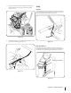
7 Service Belt Replacement 3. Auger Belt Carefully pivot the snow thrower up and forward so that it rests on the auger housing. 4. Remove the frame cover from the underside of the snow thrower by removing four self-tapping screws which secure it. See Fig 7-3. To remove and replace your snow thrower’s auger belt, proceed as follows: 1. To prevent spillage, place a piece of plastic wrap under the gas cap and tighten securely. 2.
6. Remove the belt from around the auger pulley, and slip the belt between the support bracket and the auger pulley. See Fig. 7-5. Drive Belt To remove and replace your snow thrower’s drive belt, proceed as follows: 1. Place a piece of plastic under the gas cap. 2. Remove the plastic belt cover on the front of the engine by removing the two self-tapping screws. Refer to Fig. 7-1. 3. Remove the belt as follows. See Fig. 7-6.: a. Roll the auger belt off the engine pulley. b.
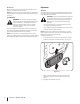
6. Slip the drive belt off the pulley and between friction wheel and friction wheel disc. See Fig. 7-7. Friction Wheel Removal If the snow thrower fails to drive with the drive control engaged, and performing the drive control cable adjustment fails to correct the problem, the friction wheel may need to be replaced. Follow the instructions below. Examine the friction wheel for signs of wear or cracking and replace if necessary: 1. Place a piece of plastic under the gas cap. 2.
5. Carefully remove the hex nut which secures the hex shaft to the snow thrower frame and lightly tap the shaft’s end to dislodge the ball bearing from the right side of the frame. See Fig. 7-9. NOTE: Be careful not to damage the threads on the shaft. Follow the previous steps in reverse order to reassemble components. If you’re disassembling the friction wheel and replacing only the rubber ring, proceed as follows: 1. Figure 7-11 Figure 7-9 6.
87 Troubleshooting Problem Engine fails to start Cause 1. Choke not in ON position. 1. Move choke to ON position. 2. Spark plug wire disconnected. 2. Connect wire to spark plug. 3. Fuel tank empty or stale fuel. 3. Fill tank with clean, fresh gasoline. 4. Engine not primed. 4. Prime engine as instructed in “Operating Your Snow Thrower”. 5. Faulty spark plug. Engine runs erratic 5. Clean, adjust gap, or replace. 6. Blocked fuel line. 6. Clean fuel line. 7. Safety key not in ignition on engine.
9 Replacement Parts Component Part Number and Description 929-0071 Extention Cord, 110V 954-04050 754-0367 Auger Drive Belt Wheel Drive Belt 684-04153 935-04054 Friction Wheel Assembly Friction Wheel Rubber 925-04213 Lamp, 12.5V, 37.5W 738-04124A 714-04040 Shear Pin, 1.
CUB CADET LLC MANUFACTURER’S LIMITED WARRANTY FOR snow throwers The limited warranty set forth below is given by Cub Cadet LLC with respect to new merchandise purchased and used in the United States, its possessions and territories, and by MTD Products Limited with respect to new merchandise purchased and used in Canada and/or its territories and possessions. c.