Operator’s Manual SERIES 5000 TRACTOR MODEL 5252 w/60" MOWER DECK IMPORTANT: READ SAFETY RULES AND INSTRUCTIONS CAREFULLY Warning: This unit is equipped with an internal combustion engine and should not be used on or near any unimproved forest-covered, brush-covered or grass-covered land unless the engine’s exhaust system is equipped with a spark arrester meeting applicable local or state laws (if any). If a spark arrester is used, it should be maintained in effective working order by the operator.
TABLE OF CONTENTS TO THE OWNER .................................................................................................................... 2 CALLING SERVICE INFORMATION ...................................................................................... 2 RECORDING MODEL AND SERIAL NUMBER INFORMATION ........................................... 3 IMPORTANT SAFE OPERATION PRACTICES ..................................................................... 4 SAFETY LABELS ................................
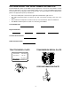
RECORDING MODEL AND SERIAL NUMBER INFORMATION Product identification plates are provided for major components of your tractor. The numbers on these plates are important if your tractor should require dealer service, or if you need additional information on your tractor. Prior to using your tractor for the first time, record the numbers from the identification plates in the appropriate spaces provided below. • The tractor model plate is located on the right frame rail behind the right front tire.
IMPORTANT SAFE OPERATION PRACTICES WARNING: THIS SYMBOL POINTS OUT IMPORTANT SAFETY INSTRUCTIONS WHICH, IF NOT FOLLOWED, COULD ENDANGER THE PERSONAL SAFETY AND/OR PROPERTY OF YOURSELF AND OTHERS. READ AND FOLLOW ALL INSTRUCTIONS IN THIS MANUAL BEFORE ATTEMPTING TO OPERATE YOUR UNIT. FAILURE TO COMPLY WITH THESE INSTRUCTIONS MAY RESULT IN PERSONAL INJURY. WHEN YOU SEE THIS SYMBOL, HEED ITS WARNING.
• • • • • • • • • • • • • • • Disengage all attachment clutches, thoroughly depress the brake pedal and shift into neutral before attempting to start the engine. Your mower is designed to cut normal residential grass of a height no more than 10”. Do not attempt to mow through unusually tall, dry grass (e.g. pasture) or piles of dry leaves. Debris may build up on the mower deck or contact the engine exhaust presenting a potential fire hazard.
3. CHILDREN • • • • Tragic accidents can occur if the operator is not alert to the presence of children. Children are often attracted to the machine. Never assume children will remain where you last saw them. Never attempt to straighten or reweld any part of the main frame or retaining brackets that have been damaged. Doing so may weaken the structure and endanger your safety. • Keep children out of the mowing area and in watchful care of an adult other than the operator.
• Keep all nuts, bolts and screws tight to be sure the equipment is in safe working condition. • Never tamper with safety devices. Check their proper operation regularly. • After striking a foreign object, stop the engine, and thoroughly inspect the mower for any damage. Repair the damage before restarting and operating the mower. • Mower blades are sharp and can cut. Wrap the blades or wear gloves, and use extra caution when servicing blades. • Check brake operation frequently.
SAFETY LABELS WARNING WARNING AVOID SERIOUS INJURY OR DEATH To avoid personal injury, keep PTO shield in place. Pull only from draw bar. pulling from any other point can cause rear overturn. Disengage PTO and stop engine before servicing tractor, or implements, or attaching or detaching implements. FAILURE TO FOLLOW ANY OF THE INSTRUCTIONS ABOVE CAN CAUSE SERIOUS INJURY TO THE OPERATOR, OR OTHER PERSONS. DIE OUTLINE DOES NOT PRINT 1. GO UP AND DOWN SLOPES, NOT ACROSS. 2. AVOID SUDDEN TURNS. 3.
SECTION 1: CONTROLS AND FEATURES W X A B V C D U HOURS 1/10 FUEL RPM 0 E x1000 4 E F T F S R G H H Q J P K O L L M N Figure 1 A. B. C. D. E. F. G. Steering Wheel Throttle Handle PTO Switch Ignition Switch Brake Pedal Reverse Pedal Forward Pedal H. J. K. L. M. N. O. P. Hand Holds Hydraulic Lift Lever Cup Holder Amber Hazzard Light Seat Adjustment Lever Seat Belt Fuel Fill Cap Trans. Hi/Lo Shift Lever Q. R. S. T. U. V. W. X.
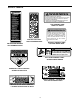
NOTE: References to LEFT and RIGHT indicate OFF that side of the tractor when facing forward while seated in the drivers seat. Reference to FRONT indicates the grille end of the tractor; to REAR, the tow plate end. STOP ON START A. Steering Wheel The steering wheel is centered on the dash panel, and used to change the direction (left or right) of the tractor while driving. Figure 3 OFF - The engine and electrical system is turned off.
O. Fuel Fill Cap The fuel fill cap is located on the left fender beside the operator’s seat. G. Forward Pedal Forward Pedal Symbol P. Transmission Hi/Lo Range Shift Lever The Hi/Lo range shift lever is located on the left fender. The lever has two speed range settings and a neutral position. The lever must be shifted into either the high or low range prior to depressing the forward or reverse pedal to drive the tractor. • Push the lever fully forward to shift into the high range.
U. Hazard Light Switch S. Differential Lock Pedal Diff. Lock Pedal Symbol Figure 10 Figure 8 The hazard light switch is a rocker type switch located to the left of the steering wheel on the dash panel. Push the top of the hazard light switch downward to activate the flashing amber lights. Located at the front of the left running board, the differential lock pedal engages the transmission differential lock.
X. Instrument Panel 7 3 Green Range 4 2 1 HOURS 1/10 RPM FUEL E F 0 5 x1000 4 6 Figure 12 5. PTO Engaged Indicator This indicator illuminates whenever the PTO switch is pulled upward in the "ENGAGED" position while the key switch is turned to the "ON" position. Check this indicator if the engine will not crank with the key switch in the "START" position—the indicator should not be illuminated. If necessary, move the PTO switch to the "DISENGAGED" position. 1.
SECTION 2: OPERATION ROLLOVER PROTECTIVE STRUCTURE (ROPS) SAFETY INTERLOCK SYSTEM This tractor is equipped with a Rollover Protection Structure (ROPS) and seat belts. When used together they are effective in reducing injuries to the operator in the event of an accidental tractor rollover. The safety provided by the ROPS is minimized if the seat belt is not properly adjusted AND buckled. Refer to ADJUSTMENTS for seat belt adjustment.
• WARNING: Gasoline is extremely flammable and can be explosive in certain conditions. Do not fill the fuel tank when the engine is running or while the engine is hot. Tighten the fuel cap securely. Make sure the PTO switch is in the “OFF” position. NOTE: The PTO light on instrument panel will be lit if switch is in the "ON" position. THROTTLE HANDLE SLOW The fuel fill cap is located on the fender to the left of the seat. Unscrew the fuel cap and fill tank from an approved gasoline container.
• Allow the engine to run for a few minutes at mid throttle before putting the engine under load. • Observe the instrument panel. If the battery indicator light or oil pressure light come on, immediately stop the engine. Have the tractor inspected by your Cub Cadet dealer. DRIVING THE TRACTOR WARNING: Avoid sudden starts, excessive speed and sudden stops. WARNING: Do not leave the seat of the tractor without disengaging the PTO and engaging the parking brake.
USING THE HI/LO RANGE SHIFT LEVER USING THE FORWARD AND REVERSE PEDALS WARNING: The tractor must be stopped before engaging or disengaging the transmission Hi/Lo range shift lever. Shifting while the tractor is in motion will cause damage to the transmission. The hydrostatic transmission provides constantly variable ground speeds within the speed rating of each (HI/LO) transmission range. The tractor speed is controlled by the forward and reverse pedals on the front of the right running board.
IMPORTANT: Do not engage the differential lock when one of the rear wheels is rotating. Stop the wheel rotation and then engage the differential lock. DRIVING ON SLOPES WARNING: Do not operate on inclines with a slope in excess of 15 degrees (a rise of approximately 2-1/2 feet every 10 feet). The tractor could overturn and cause serious injury. WARNING: When operating with the differential lock engaged, the tractor will be difficult to steer.
ENGAGING THE PTO USING THE HYDRAULIC LIFT LEVER WARNING: The operator must be in the seat at all times when the PTO is engaged. If the operator should leave the seat without turning off the PTO switch, the tractor’s engine will shut off. The hydraulic lift system provides power for raising and positioning three point hitch and belly mounted equipment. To raise an attachment using the hydraulic lift system, the engine must be running. Generally, an attachment can be lowered with the engine running or off.
Use of the headlights, along with a SMV (Slow Moving Vehicle) emblem, is also recommended when operating the tractor on or near roadways to increase visibility to traffic. USING THE PTO REVERSE OVERRIDE SWITCH The PTO reverse override switch, located on the left fender, allows the PTO to operate while the tractor is traveling in the reverse direction. See Figure 20.
IMPORTANT: When transporting pull-behind equipment on public roadways, always use a safety chain to supplement the connection between the tractor and towed equipment. The safety chain must have a strength rating equal to or greater than the gross weight of the equipment being towed. REMOVING THE REAR PTO COVER The rear PTO cover is a safety feature designed to prevent items from accidentally being caught by the rotating shaft. The cover should be removed only when the rear PTO is being utilized.
Front Weights To counterbalance three point hitch mounted equipment, a weight bracket/bumper kit and cast iron weights are available from your Cub Cadet dealer. Refer to the Weighting Table for the proper ballast to be added to the front of the tractor. TRACTOR WEIGHTING When implements are installed on either the front or rear of the tractor, the normal balance of the tractor is altered.
SECTION 3: ADJUSTMENTS Adjust the final length of the seat belt using the adjuster clip, buckle link, and upper belt webbing on the right half of the belt. ADJUSTING THE SEAT For the comfort of the operator, a single lever adjustable seat is provided to set the fore to aft position of the seat. Adjust the seat to the most comfortable position that allows you to operate all controls and pedals.
• • The length of the upper hitch link is normally determined by the design of each implement. To adjust the upper hitch link, loosen the locking lever and turn the adjustment tube as shown in Figure 27. After the appropriate length is attained, tighten the locking lever. If correctly adjusted, the upper hitch link will be parallel or nearly parallel to the lower hitch links. Distance ‘A’ should be 1/8"-1/4" less than distance ‘B’ if the toe-in is correct. If it is not, readjust the toe-in.
puck and the brake disc. The gap should measure between .012 and .015". See Figure 31. ADJUSTING THE BRAKES The tractor brakes are adjusted at the factory and should experience minimal wear if the tractor is operated normally. However, all brake pads are subject to wear and at some point the brake linkage may have to be adjusted. • If the gap is greater than .015", tighten the hex nut on the brake assembly until the gap is within the tolerance.
SECTION 4: TRACTOR MAINTENANCE Apply pressure until clean grease emerges from the lubrication point. Miscellaneous working parts not provided with lubrication fittings should be oiled regularly with a good grade of lubricating oil. The service life and reliability of any machine depends upon the care it is given. Proper lubrication and maintenance is a vital part of that care.
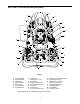
LUBRICATION AND MAINTENANCE CHART (ILLUSTRATION) 18 9 9 7 6 11 4 1 2 3 10 16 15 12 8 17 4 5 4 13 12 13 5 27 14
LUBRICATION AND MAINTENANCE CHART Check Engine Oil Level 2 Check Air Cleaner 3 Clean Air Cleaner Foam Precleaner Element 4 Change Engine Oil and Replace Oil Filter 5 Retorque Front Wheel Lug Bolts and Rear Wheel Lug Nuts 6 Check Transmission Oil Level 7 Replace Hydrostatic Transmission Oil Filter first 25 hours 8 Replace Hydraulic System Filter first 25 hours 9 Replace Hydraulic/Hydrostatic Oil 10 Replace Air Cleaner Paper Element Grease Drive Shaft (both ends) 12 Grease Front Steerin
• ACCESSING THE ENGINE COMPARTMENT WARNING: If the tractor has been recently operated, engine surfaces (including the radiator) will be HOT. Allow the engine to cool before opening the hood, or use extreme caution to avoid burns when the hood is open. • • To raise the hood, locate the hood latch below the hood notch at the front of the tractor. Pull the hood latch upward to release the front of the hood. See Figure 32. • Keep all sources of ignition (cigarettes, matches, lighters) away from the battery.
• • BATTERY STORAGE Repeat the above procedure to remove the cable and cover from the positive battery post (marked POS). • When storing the tractor for extended periods, disconnect the negative battery cable. It is not necessary to remove the battery. • All batteries discharge during storage. Keep the exterior of the battery clean, especially the top. A dirty battery will discharge more rapidly. • The battery must be stored with a full charge.
Main Fuse The main fuse in the tractor wire harness protects the tractor’s entire electrical system. A blown main fuse will prevent battery current from passing though the harness. HAZARD BULB REPLACEMENT Hazard lights are installed on each side of the ROPS. To replace the bulbs proceed as follows: • Insert a thin bladed screwdriver, or similar tool, between an amber lense and the hazard light body, then twist to separate the lense from the body. Refer to Figure 35.
Electrical Circuit Relays Several relays, which operate electrical functions of the tractor, are located inside the lower dash panel. If one of the circuits is not functioning properly, have your dealer electrically check the relay. See Figure 39. • Start Relay — Functions in the start circuit. • PTO Relay — Operates in conjunction with both the Reverse Relay and Reverse Override Relay to engage the PTO. • Reverse Relay — Functions with the PTO Relay and Reverse Switch in the "No Cut in Reverse" circuit.
• Turn the oil fill plug counterclockwise to unscrew from the transmission housing. • Insert a funnel (preferably one with a flexible spout) into the fill hole of the transmission housing. • Add Cub Cadet Drive System Plus oil until the oil level can be seen through the sight glass. Do not overfill the transmission. • HYDRO TRANSMISSION FILTER ACCESS HOLE IN FENDER IMPORTANT: Always use Cub Cadet Drive System Plus oil to ensure correct formulation.
dry capacity of the transmission/hydraulic system is approximately 20 quarts. HYDRAULIC SYSTEM OIL FILTER Change the transmission/hydraulic system oil as follows: TRANSMISSION DRAIN PLUG Figure 43 • Apply a light coating of clean transmission oil to the gasket of the new hydraulic system oil filter. • Operate the tractor for a short period to warm the oil to the normal operating temperature. Place the tractor on a level surface and engage the parking brake.
LUBRICATION OF DRIVE SHAFT • Do not inflate a tire above the maximum pressure shown either on the sidewall of the tire or the Tire Inflation chart. • Do not reinflate a tire that has been run flat or seriously under inflated. Have a qualified tire mechanic inspect and service the tire. Lubricate both ends of the drive shaft after every 50 hours of operation as follows: • • The front end of the drive shaft can be accessed from under the hood, and the rear end from beneath the tractor.
Using a fuel stabilizer: • Read the product manufacturer’s instructions and recommendations. MAINTENANCE OF THE ROLLOVER PROTECTIVE STRUCTURE (ROPS) Periodically (at least every six months) visually inspect the ROPS for damage and loose fasteners. If damage is noted, contact your Cub Cadet dealer. • Add to clean, fresh gasoline the correct amount of stabilizer for the capacity (approximately 6 gallons) of the fuel system.
SECTION 5: ENGINE INFORMATION AND MAINTENANCE KOHLER CO. FEDERAL AND CALIFORNIA EMISSION CONTROL SYSTEMS LIMITED WARRANTY SMALL OFF-ROAD EQUIPMENT ENGINES The U.S. Environmental Protection Agency (EPA), the California Air Resources Board (CARB), and Kohler Co. are pleased to explain the Federal and California Emission Control Systems Warranty on your small off-road equipment engine.
ENGINE MAINTENANCE DIPSTICK WARNING: Use care when servicing any component in the engine area. If the engine has recently been operated, components will be hot and could cause burns. Allow the engine to cool before servicing. OIL FILL CAP WARNING: Before servicing the engine, place the tractor on a level surface, stop the engine, engage the parking brake, and remove the key from the ignition switch. For additional safety, remove the spark plugs to prevent accidental starting.
• Place the tractor on a level surface and engage the parking brake. Stop the tractor engine and remove the ignition key. • Clean the area around the oil filler cap to prevent debris from entering the crankcase. Refer to Figure 45. • Turn the oil filler cap a quarter turn counterclockwise to remove from the right valve cover. • SLOWLY pour oil into the crankcase until the oil level reaches the “FULL” mark on the dipstick. Refer to Figure 46.
• Start the engine and run for about 3 minutes. Stop the engine and check for leaks at the oil filter and drain valve. • Recheck the oil level and, if needed, add oil to bring the oil level up to the "FULL" mark. See Figure 48 for assembly of the air cleaner elements. WARNING: Operating the engine with loose or damaged air cleaner components will allow unfiltered air into the carburetor, causing extensive wear and eventual failure of the engine. WARNING: Never overfill the engine crankcase.
• Slip the precleaner fully onto the paper element and reinstall the paper element onto the air cleaner base. • Install the element cover and secure with the wing nut. • Reinstall the air cleaner cover and secure with the retainer knob. .030 in. gap IMPORTANT: Properly cleaned and installed air cleaner elements significantly contribute to prolonging engine life.
SECTION 6: MOWER DECK heights are not within 1/16 inch, the deck must be leveled. Note which blade had the larger distance between the cutting edge and level surface. DECK LEVELING ADJUSTMENTS The 60" mower deck is equipped with ground following front caster wheels and is designed to be operated with the front caster wheels and rear gauge wheels on the ground. However, to ensure an even cut on all types of terrain, the mower deck should be properly leveled.
Front To Back Leveling The front to back pitch of the deck is normally determined by the deck wheels when the deck is operated as designed with its wheels on the ground. However, the deck pitch should be checked to ensure an even cut when mowing uneven terrain, or when mowing with the deck wheels off the ground. REAR CUTTING EDGE B When properly leveled, the pitch of the deck will result in the front and rear cutting edges of the blades being even, to a maximum of 1/4 inch lower in the front.
SETTING THE CUTTING HEIGHT • The deck cutting height is set by positioning the left and right caster wheel axles in one of the five index hole settings of the deck height adjustment bracket. The index hole settings range in 1/2 inch increments from a cutting height of approximately 1-1/2 inches (top hole) to 3-1/2 inches (bottom hole). If a higher cutting height is desired, the deck will have to be suspended from the tractor’s lift system. Use the system’s lift lever to set the deck cutting height.
INTERNAL COTTER PIN LH FRAME MTG. PLATE CLEVIS PIN CHECK CHAIN DECK LIFT ARM LH LIFT ARM SIDE BRACE KLIK PIN Figure 60 Figure 58 • LOCKING RING • Disconnect the fixed link from the RH lift arm by removing the internal cotter pin and clevis pin. Reinstall the clevis pin and internal cotter pin in the fixed link to avoid their loss. See Figure 59. INTERNAL COTTER PIN Roll the deck forward to disengage the deck hanger rod from the slots of the deck front roller bracket.
• From either side of the tractor, lift the deck hanger rod and roll the deck forward until the hanger rod aligns with slots of the deck front roller bracket. Lower the hanger rod into the front roller bracket slots and slide the deck rearward to engage the rod fully forward in the slots of the roller bracket. Refer to Figure 61. • If installed, remove the two klik pins from the pins of LH and RH frame mounting plates.
Once a month remove the hex cap screws and belt covers to remove any accumulation of grass clippings from around the spindle pulleys and V-belt. Clean more often when mowing tall, dry grass. DECK MAINTENANCE Cleaning And Blade Care Use the Deck Wash System as follows: WARNING: When using the deck wash, never engage the deck from any position other than the operator’s seat of the tractor. Do not use an assistant or engage deck in the presence of bystanders.
6 1 3&4 2 5 4 3&4 2 1 6 1. Spindle Belt Covers 2. Hex Cap Screws 3. Button Plugs - Access to Spindle Lube Fitting 4. Spindle Assembly Lube Fittings 5. Idler Arm Lube Fitting 6. Height Adjustment Brackets Figure 66 • Push the movable flat idler pulley (2, Figure 67) toward the left side of the deck to relieve tension from the belt. Slip the spindle belt off the movable flat idler pulley, then carefully release the flat idler pulley.
1 4 1 5 6 8 2 1 3 9 7 9 10 1. 2. 3. 4. 5. 6. 7. 8. 9. 10. Spindle Pulleys Movable Flat Idler Pulley Drive Pulley Fixed Flat Idler Pulley Spindle Belt LH Belt Cover Mntg. Strap Gear Box Mntg. Bracket Idler Arm Hex Cap Screws Deck Mounting Plate Figure 67 5. Route the belt as follows: • around the left spindle pulley • around the rear of the fixed flat idler pulley • around the front of the center spindle pulley • to the right spindle pulley Install New Spindle Belt 1.
Lubricant is cheap. Use plenty of it. Worn parts can be expensive to replace. MOWER DECK LUBRICATION GUIDE NOTE: We do not recommend the use of a pressure washer or garden hose to clean your unit. They may cause damage to spindles; pulleys; or bearings. The use of water will result in shortened life and reduce serviceability. Keep your supply of lubricating oil and grease stored in clean containers, and covered to protect from dust and dirt.
Streaking may occur when attempting to mow heavy weeds and tall grass. Under these conditions it may be necessary to go back over the cut area a second time to get a clean cut. MOWING WARNING: To avoid possible injury, never direct the discharge of material toward bystanders or allow anyone near the machine while in operation. Although the area has been supposedly cleared of foreign objects, small objects may be picked up and discharged by the mower.
SECTION 7: SPECIFICATIONS Engine Manufacturer. . . . . . . . . . . . . . . . . . . . . . . . . . . . . . . . . . . . . . . . . . . . . . . . . . . . . . . . . . . . Kohler Horsepower . . . . . . . . . . . . . . . . . . . . . . . . . . . . . . . . . . . . . . . . . . . . . . . . . . . . . . . . . . . . . . . 25 Cylinders . . . . . . . . . . . . . . . . . . . . . . . . . . . . . . . . . . . . . . . . . . . . . . . . . . . . . . . . . . . . . . . 2 OHV Cooling System. . . . . . . . . . . . . . . . . . . . . .
SPECIFICATIONS Hydraulic Lift System Type . . . . . . . . . . . . . . . . . . . . . . . . . . . . . . . . . . . . . . . . . . . . . . . . . . . . . . . . . . . Auxiliary Pump Control . . . . . . . . . . . . . . . . . . . . . . . . . . . . . . . . . . . . . . . . . . . . . . . . . . . Fender Mounted Lever Pump Capacity . . . . . . . . . . . . . . . . . . . . . . . . . . . . . . . . . . . . . . . . . . . . . . . . . . . . . 5.5 gal./min. Maximum Pressure . . . . . . . . . . . . . . . . . . . . . . . . . . . .
SECTION 8: OPTIONAL EQUIPMENT AND ACCESSORIES When purchasing your tractor, you probably had it equipped for your particular needs at that time. You may later wish to obtain additional equipment or accessories to perform other tasks. Refer to the chart below for a list of approved optional equipment and accessories currently available through your Cub Cadet dealer.
CALIFORNIA EMISSION CONTROL WARRANTY STATEMENT YOUR WARRANTY RIGHTS AND OBLIGATIONS The California Air Resources Board and MTD Consumer Group Inc are pleased to explain the evaporative emission control system warranty on your 2006 lawn mower. In California, new lawn mower must be designed, built and equipped to meet the State’s stringent anti-smog standards.
CUB CADET LLC MANUFACTURER’S LIMITED WARRANTY FOR 5000, 6000, & 7500 SERIES COMPACT TRACTORS AND CUB CADET ATTACHMENTS IMPORTANT: To obtain warranty coverage owner must present an original proof of purchase and applicable maintenance records to the servicing dealer. Please see the operator’s manual for information on required maintenance and service intervals. Without limiting the foregoing, this limited warranty does not provide coverage in the following cases: a.