Safe Operation Practices • Set-Up • Operation • Maintenance • Service • Troubleshooting • Warranty Operator’s Manual Two-Stage Snow Thrower — 524 SWE WARNING READ AND FOLLOW ALL SAFETY RULES AND INSTRUCTIONS IN THIS MANUAL BEFORE ATTEMPTING TO OPERATE THIS MACHINE. FAILURE TO COMPLY WITH THESE INSTRUCTIONS MAY RESULT IN PERSONAL INJURY. CUB CADET LLC, P.O. BOX 361131 CLEVELAND, OHIO 44136-0019 Printed In USA Form No.
1 To The Owner Thank You Thank you for purchasing a Snow Thrower manufactured by Cub Cadet LLC. It was carefully engineered to provide excellent performance when properly operated and maintained. Please read this entire manual prior to operating the equipment. It instructs you how to safely and easily set up, operate and maintain your machine. Please be sure that you, and any other persons who will operate the machine, carefully follow the recommended safety practices at all times.
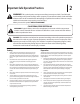
Important Safe Operation Practices 2 WARNING! This symbol points out important safety instructions which, if not followed, could endanger the personal safety and/or property of yourself and others. Read and follow all instructions in this manual before attempting to operate this machine. Failure to comply with these instructions may result in personal injury. When you see this symbol.
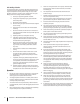
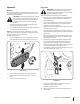
Safe Handling of Gasoline 5. To avoid personal injury or property damage use extreme care in handling gasoline. Gasoline is extremely flammable and the vapors are explosive. Serious personal injury can occur when gasoline is spilled on yourself or your clothes which can ignite. Wash your skin and change clothes immediately. Never run an engine indoors or in a poorly ventilated area. Engine exhaust contains carbon monoxide, an odorless and deadly gas. 6.
Maintenance & Storage Do not modify engine 1. Never tamper with safety devices. Check their proper operation regularly. Refer to the maintenance and adjustment sections of this manual. 2. Before cleaning, repairing, or inspecting machine disengage all control levers and stop the engine. Wait until the auger/impeller come to a complete stop. Disconnect the spark plug wire and ground against the engine to prevent unintended starting. To avoid serious injury or death, do not modify engine in any way.
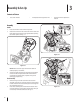
3 Assembly & Set-Up Contents of Carton • One Snow Thrower • Two Replacement Auger Shear Pins • One Snow Thrower Operator’s Manual Assembly Handle 1. Place the shift lever in the Forward-6 position 2. Observe the lower rear area of the snow thrower to be sure both cables are aligned with roller guides before pivoting the handle upward. See Fig. 3-1. 1 Figure 3-2 Figure 3-1 NOTE: Make certain the upper ends of each cable are seated properly in its bracket. 3.
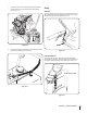
3. Finish securing chute control assembly to chute support bracket with wing nut and hex screw removed earlier. See See Fig. 3-4. Set-Up Shear Pins A pair of replacement auger shear pins and bow tie cotter pins are included with your snow thrower. Store them in your snow thrower’s dash panel until needed. See Fig. 3-5. Figure 3-4 4. Check that all cables are properly routed through the cable guide on top of the engine. See Fig. 3-5.
Tire Pressure Adding Fuel Warning! Use extreme care when handling Before operating, check tire pressure and reduce pressure in both tires to between 15 psi and 20 psi. gasoline. Gasoline is extremely flammable and the vapors are explosive. Never fuel the machine indoors or while the engine is hot or running. Extinguish cigarettes, cigars, pipes and other sources of ignition.
Adjustments Auger Control Warning! Prior to operating your snow thrower, Skid Shoes The snow thrower skid shoes are adjusted upward at the factory for shipping purposes. Adjust them downward, if desired, prior to operating the snow thrower. Caution: It is not recommended that you operate this snow thrower on gravel as it can easily pick up and throw loose gravel, causing personal injury or damage to the snow thrower and surrounding property.
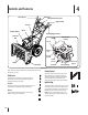
4 Controls and Features Shift Lever Drive Control Chute Directional Control Auger Control Gas Cap Chute Assembly Oil Fill Steering Trigger Control Clean Out Tool Mu r Recoil Starter Handle Primer Ignition Key Throttle Control Choke Control Augers Skid Shoe Oil Drain Electric Outlet Figure 4-1 Snow thrower controls and features are described below and illustrated in Fig. 4-1.
Throttle Control Auger Control The throttle control is located on the rear of the engine. It regulates the speed of the engine and will shut off the engine when moved into the STOP position. Primer Pressing the primer forces fuel directly into the engine’s carburetor to aid in coldweather starting. Oil Fill Engine oil level can be checked and oil added through the oil fill. Oil Drain Engine oil can be drained through the oil drain. The auger control is located on the left handle.
Chute Directional Control Chute Clean-Out Tool Warning! Never use your hands to clear a clogged chute assembly. Shut off engine and remain behind handles until all moving parts have stopped before unclogging. The chute clean-out tool is conveniently fastened to the rear of the auger housing with a mounting clip.
5 Operation Starting the Engine 3. WARNING! Always keep hands and feet clear of moving parts. Do not use a pressurized starting fluid. Vapors are flammable. Plug the extension cord into the electric outlet located on the engine. Plug the other end of extension cord into a three-prong 120-volt, grounded, AC outlet in a wellventilated area. See Fig. 5-2. NOTE: Allow the engine to warm up for a few minutes after starting. The engine will not develop full power until it reaches operating temperatures.
Recoil Starter Caution! Do not pull the starter handle while the engine running. To Steer 1. With the drive control engaged, squeeze the right steering trigger control to turn right. Squeeze the left steering trigger control to turn left. Caution: Operate the snow thrower in open areas and at slow speeds until you are familiar with the drive control and comfortable operating the steering controls. WARNING: To avoid unsupervised engine operation, never leave the engine unattended while running.
6 Maintenance & Adjustments Maintenance Lubrication Engine Gear Shaft Refer to the Engine Maintenance section. The gear (hex) shaft should be lubricated at least once a season or after every twenty-five (25) hours of operation. Shave Plate and Skid Shoes The shave plate and skid shoes on the bottom of the snow thrower are subject to wear. They should be checked periodically and replaced when necessary. 1. Carefully pivot the snow thrower up and forward so that it rests on the auger housing. 2.
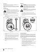
Auger Shaft Adjustments At least once a season, remove the shear pins from the auger shaft. Spray lubricant inside the shaft and around the spacers along the shaft. Using a grease gun, apply two strokes of grease (Part Number 737-0168A) to the fitting found at each end of shaft. See Fig. 6-3. Shift Cable Vent Plug If the full range of speeds (forward and reverse) cannot be achieved, adjust the shift cable as follows: 1. Place the shift lever in the fastest forward speed position. 2.
Drive Control Chute Directional Control When the drive control is released and in the disengaged “up” position, the cable should have very little slack. It should NOT be tight. If the chute assembly does not have full range from left-to-right, the chute control cables can be adjusted to take up slack: NOTE: If excessive slack is present in the drive cable or if the snow thrower’s drive is disengaging intermittently during operation, the cable may be in need of adjustment. 1.
7 Engine Maintenance WARNING! To prevent accidental start-up, shut off the engine and remove the ignition key before performing any type of engine maintenance. Periodic inspection and adjustment of the engine is essential if high level performance is to be maintained. Regular maintenance will also ensure a long service life. The required service intervals and the type of maintenance to be performed are described in the table below. Follow the hourly or calendar intervals, whichever occur first.
Spark Plug 4. Check that the spark plug washer is in good condition and thread the spark plug in by hand to prevent crossthreading. 5. After the spark plug is seated, tighten with a spark plug wrench to compress the washer. WARNING! DO NOT check for spark with spark plug removed. DO NOT crank engine with spark plug removed. NOTE: When installing a new spark plug, tighten 1⁄2-turn after the spark plug seats to compress the washer.
7 Service Belt Replacement 3. Auger Belt Carefully pivot the snow thrower up and forward so that it rests on the auger housing. 4. Remove the frame cover from the underside of the snow thrower by removing four self-tapping screws which secure it. See Fig 8-3. To remove and replace your snow thrower’s auger belt, proceed as follows: 1. To prevent spillage, place a piece of plastic wrap under the gas cap and tighten securely. 2.
6. Remove the belt from around the auger pulley, and slip the belt between the support bracket and the auger pulley. See Fig. 8-5. Drive Belt To remove and replace your snow thrower’s drive belt, proceed as follows: 1. Place a piece of plastic under the gas cap. 2. Remove the plastic belt cover on the front of the engine by removing the two self-tapping screws. Refer to Fig. 8-1. 3. Remove the belt as follows. See Fig. 8-6.: a. Roll the auger belt off the engine pulley. b.
6. Slip the drive belt off the pulley and between friction wheel and friction wheel disc. See Fig. 8-7. 3. Figure 8-7 7. Remove and replace belt in the reverse order. NOTE: Engaging the drive control will ease reassembly of the belt. Remove the frame cover from the underside of the snow thrower by removing four self-tapping screws which secure it. See Fig. 8-8. Figure 8-8 4. Examine the friction wheel for signs of wear or cracking. See Fig. 8-9.
8 Troubleshooting Problem Engine fails to start Cause Remedy 1. Choke control not in ON position. 1. Move choke control to ON position. 2. Spark plug wire disconnected. 2. Connect wire to spark plug. 3. Fuel tank empty or stale fuel. 3. Fill tank with clean, fresh gasoline. 4. Engine not primed. 4. Prime engine as instructed in the Operation section. 5. Faulty spark plug. 5. Clean, adjust gap, or replace spark plug. 6. Safety key not inserted . 6. Insert key fully into the switch. 1.
9 Replacement Parts Component Part Number and Description 929-0071 Extention Cord, 110V 954-04050 754-0367 Auger Drive Belt Wheel Drive Belt 684-04159 935-04054 Friction Wheel Assembly Friction Wheel Rubber 725-1629 Lamp, 12.8V 738-04124A 714-04040 Shear Pin, 1.
Notes 10 25
Cub Cadet LLC (Cub Cadet), The United States Environment Protection Agency (U. S. EPA) Emission Control System Warranty Statement (Owner’s Defect Warranty Rights and Obligations) The U. S. EPA and Cub Cadet are pleased to explain the emissions control system warranty on your model year 2005 and later small off-road engine. New small off-road engines must be designed, built and equipped to meet the stringent anti-smog standards.
(7) The engine manufacturer is liable for damages to other engine components proximately caused by a failure under warranty of any warranted part. (8) Throughout the engine’s warranty period defined in Subsection (a)(2), Cub Cadet will maintain a supply of warranted parts sufficient to meet the expected demand for such parts. (9) Any replacement part may be used in the performance of any warranty maintenance or repairs and must be provided without charge to the owner.
CUB CADET LLC MANUFACTURER’S LIMITED WARRANTY FOR snow throwers The limited warranty set forth below is given by Cub Cadet LLC with respect to new merchandise purchased and used in the United States, its possessions and territories, and by MTD Products Limited with respect to new merchandise purchased and used in Canada and/or its territories and possessions. b.