Operator’s Manual SERIES 5000 TRACTOR MODEL 5234D IMPORTANT: READ SAFETY RULES AND INSTRUCTIONS CAREFULLY Warning: This unit is equipped with an internal combustion engine and should not be used on or near any unimproved forest-covered, brush-covered or grass-covered land unless the engine’s exhaust system is equipped with a spark arrester meeting applicable local or state laws (if any). If a spark arrester is used, it should be maintained in effective working order by the operator.
TABLE OF CONTENTS TO THE OWNER .................................................................................................................... 2 CALLING SERVICE INFORMATION ...................................................................................... 2 RECORDING MODEL AND SERIAL NUMBER INFORMATION ........................................... 3 IMPORTANT SAFE OPERATION PRACTICES ..................................................................... 4 SAFETY LABELS ................................
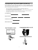
RECORDING MODEL AND SERIAL NUMBER INFORMATION Product identification plates are provided for major components of your tractor. The numbers on these plates are important if your tractor should require dealer service, or if you need additional information on your tractor. Prior to using your tractor for the first time, record the numbers from the identification plates in the appropriate spaces provided below. • The tractor model plate is located on the right frame rail behind the right front tire.
IMPORTANT SAFE OPERATION PRACTICES WARNING: THIS SYMBOL POINTS OUT IMPORTANT SAFETY INSTRUCTIONS WHICH, IF NOT FOLLOWED, COULD ENDANGER THE PERSONAL SAFETY AND/OR PROPERTY OF YOURSELF AND OTHERS. READ AND FOLLOW ALL INSTRUCTIONS IN THIS MANUAL BEFORE ATTEMPTING TO OPERATE YOUR UNIT. FAILURE TO COMPLY WITH THESE INSTRUCTIONS MAY RESULT IN PERSONAL INJURY. WHEN YOU SEE THIS SYMBOL, HEED ITS WARNING.
• • • • • • • • • • • • • • • Disengage all attachment clutches, thoroughly depress the brake pedal and shift into neutral before attempting to start the engine. Your mower is designed to cut normal residential grass of a height no more than 10”. Do not attempt to mow through unusually tall, dry grass (e.g. pasture) or piles of dry leaves. Debris may build up on the mower deck or contact the engine exhaust presenting a potential fire hazard.
3. CHILDREN • Tragic accidents can occur if the operator is not alert to the presence of children. Children are often attracted to the machine. Never assume children will remain where you last saw them. • Never secure any parts on the main frame or attach the safety frame with anything other than the special fasteners specified. • Never attach ropes, chains, or cables to the ROPS for pulling purposes. Although the ROPS provides you the maximum protection possible, never take unnecessary risks.
• Keep all nuts, bolts and screws tight to be sure the equipment is in safe working condition. • Never tamper with safety devices. Check their proper operation regularly. • After striking a foreign object, stop the engine, and thoroughly inspect the mower for any damage. Repair the damage before restarting and operating the mower. • Mower blades are sharp and can cut. Wrap the blades or wear gloves, and use extra caution when servicing blades. • Check brake operation frequently.
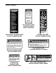
SAFETY LABELS WARNING WARNING AVOID SERIOUS INJURY OR DEATH KEEP HANDS 1. GO UP AND DOWN SLOPES, NOT ACROSS. 2. AVOID SUDDEN TURNS. 3. DO NOT OPERATE UNIT WHERE IT COULD SLIP OR TIP. 4. IF MACHINE STOPS GOING UPHILL, STOP PTO AND BACK DOWN HILL SLOWLY. 5. DO NOT MOW WHEN CHILDREN OR OTHERS ARE AROUND. 6. DO NOT ALLOW PASSENGERS ON THE TRACTOR AT ANY TIME. 7. LOOK DOWN AND BEHIND BEFORE AND WHILE BACKING. 8. KEEP SAFETY DEVICES [GUARDS, SHIELDS, AND SWITCHES] IN PLACE AND WORKING. 9.
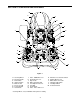
SECTION 1: CONTROLS AND FEATURES W V A U B C D T E F S H G H R J Q K P L M M O N Figure 1 A. B. C. D. E. F. G. H. Steering Wheel Throttle Handle PTO Switch Ignition Switch Brake Pedal Reverse Pedal Forward Pedal Hand Holds J. K. L. M. N. O. P. Q. Trans. 4WD Shift Lever Hydraulic Lift Lever Cup Holder Amber Hazzard Light Seat Adjustment Lever Seat Belt Fuel Fill Cap Trans. Hi/Lo Shift Lever * Steering Wheel, Seat, and ROPS Transparent for Clarity 9 R. S. T. U. V. W.
NOTE: References to LEFT and RIGHT indicate OFF - Engine and electrical system is turned off. that side of the tractor when facing forward while seated in the drivers seat. Reference to FRONT indicates the grille end of the tractor; to REAR, the tow plate end. ON - The tractor electrical system is energized. START- The starter motor will turn over the engine. Release the key immediately when the engine starts A. Steering Wheel E.
H. Hand Holds P. Fuel Fill Cap Hand holds are built into both the left and right hand fender covers. The handles can be used to assist in mounting and dismounting the tractor. The fuel fill cap is located on the left fender beside the operator’s seat. Q. Transmission Hi/Lo Range Shift Lever The Hi/Lo range shift lever is located on the left fender. The lever has two speed range settings and a neutral position.
U. Hazard Light Switch T. Differential Lock Pedal Diff. Lock Pedal Symbol Figure 9 The hazard light switch is a rocker type switch located to the left of the steering wheel on the dash panel. Push the top of the hazard light switch downward to activate the flashing amber lights. Figure 8 Located at the front of the left running board, the differential lock pedal engages the transmission differential lock.
W. Instrument Panel 3 4 7 9 5 12 10 10 1 2 8 11 6 Figure 11 1. Fuel Gauge 7. PTO Indicator Light The fuel gauge monitors, at 20 second intervals, the fuel level in the fuel tank. The needle pointing to the right indicates a full tank. The ignition switch must be in the ON position to read the fuel gauge. Light comes on in a fixed mode whenever the PTO switch is in the ON position, with the following exceptions.
SECTION 2: OPERATION ROLLOVER PROTECTIVE STRUCTURE (ROPS) SAFETY INTERLOCK SYSTEM This tractor is equipped with a Rollover Protection Structure (ROPS) and seat belts. When used together they are effective in reducing injuries to the operator in the event of an accidental tractor rollover. The safety provided by the ROPS is minimized if the seat belt is not properly adjusted AND buckled. Refer to ADJUSTMENTS for seat belt adjustment.
• • • • • • Do not smoke while refueling the tractor. Do not fill the fuel tank when the engine is running or while the engine is hot. The fuel fill cap is located on the fender to the left of the seat. Unscrew the fuel cap and fill tank from an approved container. Do not fill the fuel tank to capacity. Allow room for expansion. Tighten the fuel cap securely, and immediately wipe up any spilled fuel. To minimize condensation, keep the fuel tank as full as possible without filling to capacity.
DRIVING THE TRACTOR COLD WEATHER STARTING (BELOW 14° F) Move the throttle handle to approximately the "FAST" throttle position, then follow the normal engine starting instructions above. WARNING: Avoid sudden starts, excessive speed and sudden stops. NOTE: An optional engine coolant heater is available from your Cub Cadet dealer. This heater will aid in starting the tractor when ambient temperatures fall below 10°F (-12°C).
USING THE HI/LO RANGE SHIFT LEVER USING THE FORWARD AND REVERSE PEDALS The hydrostatic transmission provides constantly variable ground speeds within the speed rating of each transmission range. The tractor speed is controlled by the forward and reverse pedals on the front of the right running board. WARNING: The tractor must be stopped before engaging or disengaging the transmission Hi/Lo range shift lever. Shifting while the tractor is in motion will cause damage to the transmission.
DRIVING ON SLOPES WARNING: Do not operate on inclines with a slope in excess of 15 degrees (a rise of approximately 2-1/2 feet every 10 feet). The tractor could overturn and cause serious injury. DIFFERENTIAL LOCK PEDAL (Depress and Hold to Engage) IMPORTANT: Always shift the transmission into the LOW speed range BEFORE beginning the climb or descent of any slope. Operate the tractor up and down slopes, never across slopes.
USING THE HYDRAULIC LIFT LEVER THROTTLE HANDLE The hydraulic lift system provides power for raising and positioning three point hitch and belly mounted equipment. To raise an attachment using the hydraulic lift system, the engine must be running. Generally, an attachment can be lowered with the engine running or off. • Move the lift lever forward in the slot to lower the equipment to the desired height setting. Refer to Figure 18. • Move the lift lever rearward in the slot to raise the equipment.
Hazard Lights Always use the flashing amber hazard lights along with the SMV (Slow Moving Vehicle) emblem when operating the tractor on, or near, roadways. Also activate the hazard lights when necessary to warn others that the tractor is being operated in the area. • To turn on the flashing hazard lights, depress the top end of the hazard light switch located to the left of the headlight switch. • To turn off the hazard lights, depress the bottom of the light switch.
To counterbalance these weight shifts, weight should be added to the tractor in the form of either front cast iron weights, a rear weight box, and/or liquid tire ballast. Only enough weight should be added to obtain good traction, control, and stability. Excessive weight will unnecessarily load down the tractor’s engine and transmission. USING THE HITCH PLATE Use only the hitch plate (Refer to Figure 22), for towing pull-behind equipment (carts, trailers, etc.) or dragging loads.
SECTION 3: ADJUSTMENTS Adjust the final length of the seat belt using the adjuster clip, buckle link, and upper belt webbing on the right half of the belt. ADJUSTING THE SEAT For the comfort of the operator, a single lever adjustable seat is provided to set the fore to aft position of the seat. Adjust the seat to the most comfortable position that allows you to operate all controls and pedals.
• • The length of the upper hitch link is normally determined by the design of each implement. To adjust the upper hitch link, loosen the locking lever and turn the adjustment tube as shown in Figure 26. After the appropriate length is attained, tighten the locking lever. If correctly adjusted, the upper hitch link will be parallel or nearly parallel to the lower hitch links. Distance ‘A’ should be 1/8"-1/4" less than distance ‘B’ if the toe-in is correct. If it is not, readjust the toe-in.
puck and the brake disc. The gap should measure between .012 and .015". See Figure 30. ADJUSTING THE BRAKES The tractor brakes are adjusted at the factory and should experience minimal wear if the tractor is operated normally. However, all brake pads are subject to wear and at some point the brake linkage may have to be adjusted. • If the gap is greater than .015", tighten the hex nut on the brake assembly until the gap is within the tolerance.
SECTION 4: MAINTENANCE pressure lubricating gun to force in new grease. Apply pressure until clean grease emerges from the lubrication point. The service life and reliability of any machine depends upon the care it is given. Proper lubrication and maintenance is a vital part of that care. Using the Lubrication and Maintenance Chart as a guide, monitor the hourmeter on the instrument panel to ensure the required maintenance procedures are performed.
LUBRICATION AND MAINTENANCE CHART (ILLUSTRATION) 18 10 7 13 10 8 1 5 5 2 11 20 4 19 6 12 21 5 3 15 17 9 13 17 16 14 6 26 17
LUBRICATION AND MAINTENANCE CHART 1 Check Engine Oil Level 2 Check Air Cleaner 3 Check Engine Coolant Level 4 Check and Clean Radiator Screen 5 Change Engine Oil and Replace Oil Filter 6 • first 50 hrs. Retorque Front and Rear Wheel Lug Nuts Before Storage Every 400 Hours Every 300 Hours Every 200 Hours Every 150 Hours • • • • first 10 hrs.
ACCESSING THE ENGINE COMPARTMENT QUICK FASTENER WARNING: If the tractor has been recently operated, engine surfaces (including the radiator) will be HOT. Allow the engine to cool before opening the hood, or use extreme caution to avoid burns when the hood is open. Pivot Flip up Turn QUICK FASTENER To raise the hood, locate the latch release lever in the hood notch at the front of the tractor. Lift and hold the latch release lever while lifting the hood at the hood notch. See Figure 31.
CHARGING THE BATTERY BATTERY REMOVAL Test and, if necessary, recharge the battery after the tractor has been stored for a period of time. • A voltmeter or load tester should read 12.6 volts (DC) or higher across the battery terminals. WARNING: Battery posts, terminals and related accessories contain lead and lead compounds. Wash hands after handling. The battery is located at the front of the tractor beneath the hood. • Charge the battery with a 12-volt battery charger at a MAXIMUM rate of 10 amps.
HEAD LIGHT BULB REPLACEMENT The tractor is equipped with headlights. If one of the bulbs should burn out, replace the bulb as follows: LENSES NOTCH BULB SOCKET SCREW • Fully raise the hood. • Pull the wire harness plug from the bulb/socket assembly to unplug the wire harness. See Figure 34.
To replace the main fuse: • Raise tractor hood and remove right side panel. • Locate the fuse holder on the front of the bulkhead, just inside the right side of the dash panel. See Figure 39. Accessing the Fuse Center The fuse center is located on the inside right of the dash panel. To access the fuse center, remove the dash panel insert by removing the two screws. See Figure 37. To cover the fuse center, reposition the dash panel insert in the dash and secure with the two screws.
25 Hour Break-In Period Filter Change CHECKING TRANSMISSION/HYDRAULIC SYSTEM OIL LEVEL During the initial hours of tractor operation, contaminants caused by the normal break-in of internal transmission and hydraulic system components will collect in the oil filters. Because of this, both the hydro transmission and hydraulic system filters should be changed after the first 25 hours of operation. Check the hydro transmission/hydraulic system oil level before each use.
• • Remove the old hydrostatic filter by turning it counterclockwise, and immediately replace with the new filter. Turn the filter clockwise by hand until the gasket contacts the filter base; then tighten the filter an additional 1/2 to 3/4 turn. Clean any residual oil from the top of the transmission. • Remove the old hydraulic system filter by turning it counterclockwise. • If performing the 25 hour filter change, install the new filter immediately.
Dispose of used oil in an environmentally safe manner. If necessary, contact your area EPA office for proper disposal procedures and recycling center locations. • Change the hydro transmission filter as instructed in Changing Hydro Transmission Oil Filter. • Change the hydraulic system filter as instructed in Changing Hydraulic System Oil Filter. • Insert a funnel (preferably one with a flexible spout) into the fill hole in the rear of the transmission housing.
• To prevent debris from entering the front axle housing, clean the area around the oil fill plug/ dipstick and the axle drain plug located at the center front of the axle. Refer to Figure 44 and Figure 46. • Using a funnel with a flexible spout, fill the gear case up to the bottom of the fill port with Cub Cadet Gear Lube. Reinstall the fill plug. • Repeat the previous three steps to change the oil in the other final reduction gear case. Dispose of used oil in an environmentally safe manner.
TIRE MAINTENANCE • Check the tire air pressure after every 50 hours of operation or weekly. Keep the tires inflated to the recommended pressures. Improper inflation will shorten the service life of a tire. See the tire side wall, or the Tire Inflation chart, for proper inflation pressures. Observe the following guidelines: Make certain the jack used to raise the tractor has a weight capacity adequate for lifting the tractor.
6. Fully charge the battery, then disconnect the negative cable at the battery to prevent possible discharge. Thoroughly clean the battery. Recharge the battery periodically when in storage. TRACTOR STORAGE If your tractor is not going to be operated for an extended period of time (thirty days to approximately six months), the tractor should be prepared for storage. Store the tractor in a dry and protected location. If stored outside, cover the tractor (including the tires) to protect it from the elements.
SECTION 5: ENGINE INFORMATION AND MAINTENANCE Daihatsu L.L.C., the California Air Resources Board (CARB) and the United States Environmental Protection Agency (U.S.
c. Ignition System • Glow plug d. Exhaust System • Exhaust manifold e. Miscellaneous Items Used in Above Systems • Vacuum, temperature, position, time sensitive valves and switches • Electronic controls • Connectors and assemblies • Hoses 2.
CHECKING ENGINE OIL LEVEL Before each use, the oil level in the engine crankcase should be checked to see that it is filled to the correct level. During the "break in" period for the engine, closely monitor the engine oil level. The oil level should be checked hourly during the first 5 hours of operation. • Check the oil level only while the engine is stopped and the tractor is level. Clean the area around the oil level dipstick to prevent debris from entering the crankcase. See Figure 49.
• • Clean the area around the oil filler cap to prevent debris from entering the crankcase. See Figure 50. • OIL FILL CAP Remove the dipstick and oil fill cap from the engine. Refer to Figure 49 and Figure 50. Locate the engine drain plug on the bottom/ right side of the engine (See Figure 51). Place a suitable container below the drain plug to collect the old oil. OIL DRAIN PLUG Figure 50 • • • RT. FRAME RAIL Turn the oil filler cap counterclockwise to unscrew from the valve cover.
• • WARNING: It is dangerous to remove the radiator cap when the system is hot. Allow the system to cool before removing the radiator cap. Start the engine and run for about 5 minutes. Stop the engine and check for leaks at the oil filter and drain plug. Wait 3 minutes and re-check the oil level. If needed, add oil to bring the oil level up to the "FULL" mark. • • WARNING: Never overfill the engine crankcase. The engine may overheat and/or damage may result.
• • Place a suitable container beneath the drain plug and remove the cap from the overflow reservoir. COVER CLAMP COVER Turn the drain plug counterclockwise to remove. Allow as much of the old coolant as possible to drain from the system. Coolant is a toxic substance. Dispose of in an environmentally safe manner. Contact your area EPA office for proper disposal methods and recycling center locations. • Reinstall the drain plug and turn clockwise until fully tightened.
SERVICING THE FUEL FILTER WARNING: Do not service the fuel filter when tractor is hot or near any source of ignition. Allow the tractor to cool. Clamp Fuel Line AIR BLEED KNOB The tractor is equipped with an in-line fuel filter located on the right side of the engine. Diesel fuel is a toxic substance. Dispose of in an environmentally safe manner. Contact your area EPA office for proper disposal methods and recycling center locations.
SECTION 6: SPECIFICATIONS Engine Manufacturer. . . . . . . . . . . . . . . . . . . . . . . . . . . . . . . . . . . . . . . . . . . . . . . . . . . . . . . . . . Diahatsu Horsepower . . . . . . . . . . . . . . . . . . . . . . . . . . . . . . . . . . . . . . . . . . . . . . . . . . . . . . . . . . . . . . . 23 Cylinders . . . . . . . . . . . . . . . . . . . . . . . . . . . . . . . . . . . . . . . . . . . . . . . . . . . . . . . . . . . . . . . 3 OHV Cooling System. . . . . . . . . . . . . . . . . . . . . . .
SPECIFICATIONS Hydraulic Lift System Type . . . . . . . . . . . . . . . . . . . . . . . . . . . . . . . . . . . . . . . . . . . . . . . . . . . . . . . . . . . Auxiliary Pump Control . . . . . . . . . . . . . . . . . . . . . . . . . . . . . . . . . . . . . . . . . . . . . . . . . . . Fender Mounted Lever Pump Capacity . . . . . . . . . . . . . . . . . . . . . . . . . . . . . . . . . . . . . . . . . . . . . . . . . . . . . 5.5 gal./min. Maximum Pressure . . . . . . . . . . . . . . . . . . . . . . . . . . . .
SECTION 7: OPTIONAL EQUIPMENT AND ACCESSORIES When purchasing your tractor, you probably had it equipped for your particular needs at that time. You may later wish to obtain additional equipment or accessories to perform other tasks. Refer to the chart below for a list of optional equipment and accessories currently available through your Cub Cadet dealer.
LIMITED WARRANTY FOR CUB CADET COMPACT TRACTORS AND CUB CADET ATTACHMENTS Proper maintenance of your Cub Cadet equipment is the owner’s responsibility. Follow the instructions in your owner’s manual for correct lubricants and maintenance schedule. Your Cub Cadet dealer carries a complete line of genuine Cub Cadet parts and quality lubricants and filters for your equipment’s engine, transmission, chassis and attachments.