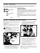
Operator’s Manual 724 WE 522 WE IMPORTANT: Read safety rules and instructions carefully before operating equipment. Warning: This unit is equipped with an internal combustion engine and should not be used on or near any unimproved forest-covered, brush-covered or grass-covered land unless the engine’s exhaust system is equipped with a spark arrester meeting applicable local or state laws (if any). If a spark arrester is used, it should be maintained in effective working order by the operator.
TABLE OF CONTENTS Content Page Important Safe Operation Practices................................................................... 3 Loose Parts........................................................................................................ 5 Assembling Your Snow Thrower........................................................................ 5 Know Your Snow Thrower ................................................................................. 7 Operating Your Snow Thrower....................
SECTION 1: IMPORTANT SAFE OPERATION PRACTICES This symbol points out important safety instructions which, if not followed, could endanger the personal safety and/or property of yourself and others. Read and follow all instructions in this manual before attempting to operate this machine. Failure to comply with these instructions may result in personal injury. When you see this symbol—heed its warning.
5. 6. 7. 8. 9. 10. 11. 12. 13. 14. 15. 16. 17. 18. 19. 20. Maintenance And Storage Never run an engine indoors or in a poorly ventilated area. Engine exhaust contains carbon monoxide, an odorless and deadly gas. Do not operate machine while under the influence of alcohol or drugs. Muffler and engine become hot and can cause a burn. Do not touch. Exercise extreme caution when operating on or crossing gravel surfaces. Stay alert for hidden hazards or traffic.
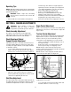
SECTION 2: LOOSE PARTS The snow thrower is shipped with following loose parts in the carton. Please remove all loose parts from the carton before discarding it. See Figure 1 to identify the parts noting that these parts may be referred to again in the following sections of this manual. Part numbers are shown in parentheses. Shear Bolts (710-0890A) Hex Lock Nuts (712-0429) AUGER SHEAR BOLTS The augers are secured to the auger shaft with two shear bolts and hex lock nuts.
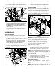
• If not already attached, slip the cables that run from the handle panel to the chute into the cable guide located on top of the engine. See Figure 4. • Recheck the adjustment before retightening the jam nut against the cable. Skid Shoe Adjustment The space between the shave plate and the ground can be adjusted by repositioning the skid shoes found on either side of the snow throwers auger housing. For close snow removal, place skid shoes in the low position.
Traction Control and Shift Lever Adjustment in need of adjustment and you should NOT operate the machine before completing the adjustment as follows: To check the adjustment of the traction control and shift lever, proceed as follows: • Loosen the jam nut on the traction control cable and UNTHREAD the cable one full turn. • Recheck the adjustment. • Retighten the jam nut to secure the cable when correct adjustment is reached.
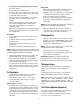
Chute Directional Control The chute directional control is located on left side of the snow thrower. Primer Choke To change the direction in which snow is thrown, turn chute directional control as follows: • • Crank clockwise to discharge to the left. Crank counterclockwise to discharge to the right. Chute Tilt Control The distance snow is thrown can be adjusted by adjusting the angle of the chute assembly. Move the chute tilt control forward to decrease the distance, toward the rear to increase.
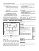
• • • • • • Recoil Starter If you have a grounded three-prong receptacle, proceed as follows. Rotate choke knob to OFF position. Connect power cord to switch box on engine. Plug the other end of power cord into a three-prong 120volt, grounded, AC receptacle. Push starter button to crank engine. As you crank the engine, move choke knob to FULL choke position. When engine starts, release starter button, and move choke gradually to OFF.
Operating Tips NOTE: Allow the engine to warm up for a few minutes as the engine will not develop full power until it reaches operating temperature. • • • • WARNING: Muffler, engine and surrounding areas become hot and can cause a burn. Do not touch. • • Set the skid shoes 1/4" below the shave plate for normal usage. The skid shoes may be adjusted upward (to lower the shave plate) for hard-packed snow. Adjust downward (to raise the shave plate) when using on gravel or crushed rock.
• • Retighten the jam nut to secure the cable when correct adjustment is reached. Reassemble the frame cover. IMPORTANT: Make certain to check for correct adjustment of the shift rod as instructed under the heading Final Adjustments on page 11 of this manual, before operating the snow thrower. Shift Rod Adjustment To adjust the shift rod, proceed as follows. Drive Wheels • The wheels may be adjusted for two different methods of operation.
Traction Control / Auger Control Lock IMPORTANT: Avoid getting oil on rubber friction wheel and aluminum drive plate. Refer to Figure 10. The cams on the ends of the control rods which interlock the traction drive and auger drive clutches must be lubricated at least once a season or every twenty-five hours of operation. The cams can be accessed beneath the handle panel. Use a multipurpose automotive grease.
SECTION 8: SERVICE WARNING: Before servicing, repairing, or inspecting, disengage all clutch levers and stop engine. Wait until all moving parts have come to a complete stop. Disconnect spark plug wire and ground it against the engine to prevent unintended starting. Belt Cover Engine Refer to the separate engine manual packed with your unit for all engine related maintenance procedures. Shave Plate and Skid Shoes The shave plate and skid shoes on the bottom of the snow thrower are subject to wear.
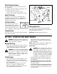
• Back out the stop bolt until the support bracket rests on the auger pulley. See Figure 20. • • Friction Wheel Friction Wheel Disc • Drive Belt • Stop Bolt Tip the snow thrower up and forward, so that it rests on the housing. Remove six self-tapping screws from the frame cover underneath the snow thrower. Remove the click pins which secure the wheels, and remove the wheels from the axle.
• Position the friction wheel assembly up onto the pin of the shift rod assembly, and slide the shaft through the assembly. Reassemble in reverse order. • WARNING: Drain fuel into an approved container outdoors, away from open flame. Allow engine to cool. Extinguish cigarettes, cigars, pipes, and other sources of ignition prior to draining fuel. Fuel left in engine for extended period deteriorates and will cause serious starting problems.
SECTION 9: TROUBLESHOOTING Problem Engine fails to start Cause 1. Fuel tank empty, or stale fuel. 2. 3. 4. 5. 6. 7. 8. Engine runs erratic Remedy 1. Fill tank with clean, fresh gasoline. Fuel becomes stale after thirty days unless a fuel stabilizer is used. Blocked fuel line. 2. Clean the fuel line. Choke not in ON position 3. Move switch to ON position Faulty spark plug. 4. Clean, adjust gap or replace. Safety key not in ignition switch on engine. 5. Insert the key fully into the switch.
SECTION 10: PARTS LIST Models 522 WE & 724 WE 4 17 11 9 16 13 8 15 1 10 14 5 18 6 3 7 12 2 Ref. No. Part No. 3 Part Description 1. 618-0123 2. 618-0418 LH Housing w/Fitting 3. 710-0642 Self Tapping Screw, 1/4-20 x .75 4. 711-1020 711-0908 Spiral Axle, 22” (522 WE) Spiral Axle, 24” (724 WE) 5. 714-0161 Hi-Pro Key, 3/16 x 5/8 6. 715-0143 Spring Spirol Pin, .25 x 1.25 7. 717-0528 Worm Gear, 20-tooth 8. 717-0526 Worm Shaft 9. 718-0186 Thrust Collar 10.
Models 522 WE & 724 WE 20 27 37 Drive Clutch Cable 39 20 5 13 7 38 37 Auger Clutch Cable 4 20 11 6 10 3 40 4 20 2 14 26 36 15 5 16 25 45 9 10 11 7 31 25 28 23 17 21 18 32 12 24 8 4 1 22 33 1 20 29 8 5 34 19 Auger Clutch Cable 26 35 46 30 1 1 44 42 42 41 43 18
Models 522 WE & 724 WE Ref. No. Part No. Ref. No. Part Description Part No. Part Description Hex Screw 25. 715-0249 Roll Pin 784-5688 Drive Cable Guide Bracket 26. 714-0143 Clik Pin 3. 784-5687A Auger Clutch Cable Bracket 27. 684-0042C Friction Wheel Assembly 4. 756-0625 Roller Cable 28. 656-0012A Friction Wheel Disc 5. 738-0924 Hex Screw 1/4-28 29. 684-0013B Wheel Shift Rod Assembly 6. 784-5630A Frame Assembly 30. 746-0897 Drive Cable 7. 741-0563 Ball Bearing 31.
Models 522 WE & 724 WE 2 3 1 4 5 11 10 9 15 18 14 12 7 8 13 32 6 31 9 18 19 20 16 22 31 43 23 27 21 10 13 30 34 28 25 23 18 13 38 26 43 35 31 22 30 18 32 31 16 41 37 33 36 17 39 40 24 40 42 39 29 20
Models 522 WE & 724 WE Ref. No. Part No. Ref. No. Part Description Part No. Part Description Lock Jam Nut 3/8-24 24. 784-5618 Bearing Housing 756-0178 Flat Idler 25. 710-0703 Carriage Screw 1/4-20 x .75 3. 784-5632A Auger Idler Arm 26. 710-0604 Hex Washer Screw 5/16-18 4. 710-0459A Hex Cap Screw 3/8-24 x 1.50 27. 736-0169 Lock Washer 3/8 5. 738-0281 Shoulder Screw 28. 712-0798 Hex Nut 3/8-16 6. 736-0174 Wave Washer 29. 741-0245 Hex Flange Bearing 7.
Models 522 WE & 724 WE 1 2 28 3 8 9 11 13 5 4 27 10 12 15 16 4 22 7 6 20 23 14 24 18 17 26 19 25 21 22
Models 522 WE & 724 WE Ref. No. Part No. Part Description 1. 710-1652 Hex Washer Screw 1/4-20 x.625 2. 731-1324 Belt Cover 3. 732-0339 Extension Spring 4. 710-0627 Hex Screw 5/16-24 x .75 5. 710-3005 Hex Cap Screw 3/8-16 x 1.25 6. 05896A Drive Clutch Bracket 7. 748-0234 Shoulder Spacer 8. 756-0985 Pulley Half 9. 754-0343 V-Belt 10. 756-0984 Pulley Half 11. 736-0270 Bell Washer 12. 710-0230 Hex Cap Screw 1/4-28 x .50 13. 756-0313 Flat Idler 14.
Models 522 WE & 724 WE 67 70 73 10 35 13 44 32 32 38 68 33 49 11 3 45 32 72 51 41 42 19 45 46 35 32 39 36 48 43 4 30 ground wire 71 (for of light ass’y) 18 34 41 54 44 69 62 47 27 55 37 43 11 11 23 29 A B 53 66 9 55 64 42 59 20 31 12 5 3 39 40 B A 15 63 65 28 21 60 24 59 6 14 26 52 4 20 12 54 18 58 61 15 7 20 11 56 55 2 17 12 57 16 25 1 8 24
Model 522 WE & 724 WE Ref. No. Part No. Ref. No. Part Description Part No. Part Description 1. 684-0008A Shift Arm Assembly 37. 732-0193 Comp. Spring, .39 x .6 x .88 2. 705-5204A Chute Crank Ass’y 38. 732-0746 Torsion Spring, .44 x .8 3. 720-0274 Handle Grip 39. 735-0199A Rubber Bumper 4. 710-0262 Carriage Bolt, 5/16-18 x 1.5 40. 736-0105 Bell Washer, .401 x .87 x .063 5. 710-0449 Carriage Bolt, 5/16-18 x 2.25 41. 736-0119 Lock Washer, 5/16 6.
Models 522 WE & 724 WE 26
MANUFACTURER’S LIMITED WARRANTY FOR: TWO-YEAR RESIDENTIAL ONE-YEAR COMMERCIAL Proper maintenance of your Cub Cadet equipment is the owner’s responsibility. Follow the instructions in your operator’s manual for correct lubricants and maintenance schedule. Your Cub Cadet dealer carries a complete line of quality lubricants and filters for your equipment’s engine, transmission, chassis and attachments.