www.mymowerparts.com Service Manual Domestic Series 5000 Compact Tractor NOTE: These materials are prepared for use by trained technicians who are experienced in the service and repair of equipment of the kind described in this publication, and are not intended for use by untrained or inexperienced individuals. Such individuals should seek the assistance of an authorized service technician or dealer. Read, understand, and follow all directions when working on this equipment.
www.mymowerparts.
www.mymowerparts.com TABLE OF CONTENTS CHAPTER 1 - Hydraulics Standard Hydraulic Systems on the Domestic Series 5000: Orientation ......................................1 Hydrostatic Drive: Basic Operation ...............................................................................................4 External Checks ............................................................................................................................6 Best Practices: Hydraulic Systems ..................................
www.mymowerparts.com CHAPTER 6 - Electrical System Similarities and Differences..........................................................................................................81 Components .................................................................................................................................82 Electric Clutch and Fuel Pump .....................................................................................................
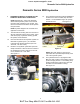
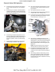
www.mymowerparts.com Domestic Series 5000 Hydraulics Domestic Series 5000 Hydraulics 1. 1.4. STANDARD HYDRAULIC SYSTEMS ON THE DOMESTIC SERIES 5000: ORIENTATION NOTE: Subsections 1 and 2 of the Domestic Series 5000 Hydraulics portion of this manual provide a basic orientation to the system. Subsection 3 and those that follow it contain specific test procedures. The hydrostatic drive filter (P/N: BS-492932S) is located on the return manifold, atop the transmission.
www.mymowerparts.com Domestic Series 5000 Hydraulics 1.6. The steering and lift cylinder are also powered by the a Sauer-Danfoss SNP 1/2.6 S auxiliary pump. 1.10. The control valve directs fluid pressure to a single-acting hydraulic cylinder that lifts the threepoint lift arms. 1.7. The steering unit, located in the dash pedestal contains it’s own back-up gerotor charge pump that will enable steering control when the engine is not running. See Figure 1.7. 1.11.
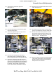
www.mymowerparts.com Domestic Series 5000 Hydraulics 1.22. From the E port, fluid will travel to the lift control valve. See Figure 1.22. 1.17. The process is reversed for right turns. See Figure 1.17. Pressure from L port (left turn) Pressure from R port (right turn) Pressure from E port Steering cylinder Figure 1.17 Figure 1.22 1.18. From the steering system, the fluid may follow one of two return paths: 1.23.
www.mymowerparts.com Domestic Series 5000 Hydraulics 1.26. When the tractor operator moves the control lever forward to lower the three point hitch, the lift control valve allows fluid to escape from the lift cylinder as the cylinder retracts under the weight of any accessories supported by the hitch. 1.27. Increased fluid volume beyond normal return flow rate is generated when the lift arms are lowered.
www.mymowerparts.com Domestic Series 5000 Hydraulics 2.5. : tilting the swash plate in one way causes the variable displacement pump to drive fluid through the fixed displacement pump in one direction. See Figure 2.5. Variable displacement pump 2.6. Tilting the swash plate the other way causes the variable displacement pump to drive fluid through the fixed displacement pump in the opposite direction. See Figure 2.6.
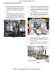
www.mymowerparts.com Domestic Series 5000 Hydraulics 3.4. 3. EXTERNAL CHECKS 3.1. If the transmission creeps, check the neutral control adjustment. See Figure 3.1. Neutral return bracket Confirm that full travel is achieved in the reverse direction. See Figure 3.4. Pedal linkage: Reverse Move shoulder bolt in slot to establish neutral Hydro linkage: Reverse Note: gap Brake linkage Figure 3.4 Figure 3.1 3.5.
www.mymowerparts.com Domestic Series 5000 Hydraulics 3.6. If the tractor fails to achieve normal ground speed, and the hydro pump emits an unusual amount of noise, check for brake drag: • Confirm that the neutral return and hydro control linkages are correctly adjusted. • With the tractor on a smooth, firm, level surface, place the gear selector in neutral, release the parking brake, and attempt to push the tractor.
www.mymowerparts.com Domestic Series 5000 Hydraulics 4. 5. BEST PRACTICES: HYDRAULIC SYSTEMS NOTE: TESTS All hydraulic tests should be done with the fluid at normal operating temperature, and the engine at normal operating speed. In practical terms, normal operating temperature means that the tractor should be operated (if not disabled) for about 5 minutes before testing in normal temperate climates.
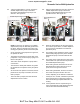
www.mymowerparts.com Domestic Series 5000 Hydraulics 5.8. The charge pressure should read at least 30 PSI (2.07 Bars) @ 1,200 RPM. See Figure 5.8. 200 PSI gauge 5.11. If the charge pressure is good, but drive has been lost in one direction only, the corresponding charge check valve may not be working. High pressure gauge • There is a charge check valve located in each circuit: one for forward, one for reverse.
www.mymowerparts.com Domestic Series 5000 Hydraulics 5.16. With the engine at a minimum speed of 1,200 RPM, fluid flow of roughly 2 GPM (7.60 LPM) should register on the meter. See Figure 5.16. 5.13. When removed, each charge relief valve comes out as a cartridge. The light compression spring provides the check valve function. The heavy compression spring provides system relief. System relief comes into play in the event of a drive system overload. See Figure 5.13.
www.mymowerparts.com Domestic Series 5000 Hydraulics other (T port). If there is pressure to the steering unit, at least one return path will have pressure. 5.21. If any mechanical problem is found with the check valve, it is to be replaced as a unit. Individual service components are not available through Cub Cadet. See Figure 5.21. 5.19. The return circuit check valve maintains a minimum pressure given sufficient flow.
www.mymowerparts.com Domestic Series 5000 Hydraulics 6.5. 6. AUXILIARY PUMP 6.1. The auxiliary pump provides pressure for the hydrostatic power steering unit, the lift cylinder attached to the three-point hitch, and any hydraulic-driven accessories that may be installed on the tractor. 6.2. Series 5000 tractors come with a single auxiliary pump mounted to the right side of the transmission. See Figure 6.2. The filter and suction tubes are easily reached for inspection with little or no disassembly.
www.mymowerparts.com Domestic Series 5000 Hydraulics 6.10. Set the parking brake, place the gear selector in neutral, open the flow valve on the gauge set all the way, and confirm that no unsafe conditions will be created by starting the tractor engine. 6.13. Close the flow valve until the pressure gauge reads 1,500 PSI (103 Bar). Note the flow reading. See Figure 6.13. 6.11. Start the engine, allow the engine and hydraulic system to warm-up. See Figure 6.11.
www.mymowerparts.com Domestic Series 5000 Hydraulics 7. STEERING PUMP AND CYLINDER 7.5. The following set of symptoms, causes, and solutions has been adapted from a list compiled by Sauer-Danfoss to aid in the diagnosis of hydrostatic steering issues. Internal steering unit problems are described to aid technicians in distinguishing internal steering unit problems from problems that lie elsewhere in the system. Internal problems dictate replacement of the steering unit.
www.mymowerparts.com Domestic Series 5000 Hydraulics • • Backlash Slow Steering: Cause 1: Wear or play between the steering column and the cardan shaft. Cause 1: Insufficient fluid flow to the steering unit. Confirm by testing the out-put of the auxiliary pump. Solution 1: If the wear is in the steering column, replace the steering column (steering shaft per Cub Cadet IPL). If the wear is in the cardan shaft, this is an internal problem.
www.mymowerparts.com Domestic Series 5000 Hydraulics • 7.10. Install the hydraulic test kit in either one of the two hydraulic lines leading from the steering pump to the steering cylinder. Steering Power Too Low: Cause 1: The relief valve is set too low or malfunctioning. 7.11. Disconnect the hydraulic line between the steering unit and the steering cylinder using a 5/8” wrench and a 3/4” wrench. See Figure 7.11. Solution 1: Internal problem; relief valve.
www.mymowerparts.com Domestic Series 5000 Hydraulics 7.15. Have an assistant slowly turn the steering wheel until the steering linkage hits the end of its travel. Applying pressure to the steering wheel while the linkage is at full lock will build pressure in the system. 7.20. To check for blow-by, turn the steering wheel in whichever direction causes the flow meter on the test kit to rise: NOTE: The wheel can be turned in either direction to get a pressure reading.
www.mymowerparts.com Domestic Series 5000 Hydraulics 8. HYDRAULIC LIFT CYLINDER AND CONTROL VALVE 8.1. If the hydraulic lift cylinder does not work or is low on power, begin by making a visual inspection of the valve, cylinder, linkage, and hydraulic hose. See Figure 8.1. Pressure line from E port Direct return to transmission Line to cylinder 8.4. If the lift cylinder is operable, run it through the full range of travel to confirm that the feedback rod is working correctly.
www.mymowerparts.com Domestic Series 5000 Hydraulics 8.6. Fluid movement: • Fluid is constantly circulating from the auxiliary pump, to the steering unit, through the valve, then to the return manifold. • • 8.7. 8.10. Confirm that the lift cylinder control valve is getting pressure from the steering pump: When the valve is actuated to raise the lift arms, it redirects fluid from this path to the lift cylinder.
www.mymowerparts.com Domestic Series 5000 Hydraulics 8.16. The flow should remain constant, while the pressure climbs to 1,500 PSI (103 Bars). Open the valve a soon as the readings are confirmed. 8.13. The flow meter should rise to 4 GPM (15 LPM) and hold steady at that level. See Figure 8.13. NOTE: Remember, the flow varies with engine RPM, but does not vary with pressure generated unless the auxiliary pump is failing. 8.17. Turn off the engine.
www.mymowerparts.com Domestic Series 5000 Hydraulics 8.22. Disconnect the flexible hydraulic line that leads from the control valve to the lift cylinder using an 11/16” and a 3/4” wrench. See Figure 8.22. 8.27. As the lift arms travel upward, note the reading on the flow meter. It should be in the vicinity of 5 GPM (19 LPM). See Figure 8.27. Disconnect here UP 4 GPM No significant pressure Figure 8.27 Figure 8.22 8.23. Connect the test kit to the 3/8” flare fittings.
www.mymowerparts.com Domestic Series 5000 Hydraulics 8.30. If the pressure delivered to the control valve is sufficient, but the pressure delivered to the cylinder is low, then the problem is likely to be in the control valve. 8.31. If the pressure delivered to the cylinder is sufficient, yet the cylinder does not perform adequately, look for leakage from the cylinder. 9.2.
www.mymowerparts.com Domestic Series 5000 Hydraulics 9.7. Reducing throttle to the 1,200-1,500 RPM range, observe the flow while pushing the loader valve lever forward to the detent. The flow should be around 5.0 GPM (19.0 LPM). 9.11. If the pressure varies slightly in above or below 1,500 PSI (103 Bars), the relief valve can be adjusted. It is located on the top, outboard corner of the loader valve. 9.8.
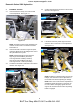
www.mymowerparts.com Domestic Series 5000 Hydraulics 9.18. Once access is gained to the adjustment screw, index the screw, jam nut, and housing using a marker. 9.16. Unbolting the loader valve bracket from the frame of the tractor will provide additional wrench clearance between the pivot bracket and the fender. This can be done with a 1/2” wrench. See Figure 9.16. 9.19. Loosen the jam nut using a 7/8” wrench and turn the adjuster screw using a 7/16” wrench. See Figure 9.19.
www.mymowerparts.com Domestic Series 5000 Hydraulics 10. COMPONENT BREAKDOWN: AUXILIARY PUMP 10.2. The back cover can be removed from the pump by removing the four socket head cap screws. See Figure 10.2. NOTE: The auxiliary pump is to be replaced as a unit if it fails. Disassembling it will VOID the warranty. The pump has been disassembled here to illustrate how it works. Pump with back cover removed Splined shaft NOTE: Individual pump components will not be available through Cub Cadet. 10.1.
www.mymowerparts.com Domestic Series 5000 Hydraulics 11. 10.7. There is a cartridge that slides into the pump body. See Figure 10.7. COMPONENT BREAKDOWN: STEERING UNIT NOTE: The steering unit is to be replaced as a unit if it fails. Disassembling it will VOID the warranty. The steering unit has been disassembled here to illustrate how it works. Second pump gear Shaft with pump gear NOTE: Individual components of the steering unit are not available through Cub Cadet. 11.1.
www.mymowerparts.com Domestic Series 5000 Hydraulics 11.4. The cardan shaft transfers motion from the steering wheel, through the body of the steering unit, to the pump. See Figure 11.4. 11.2. With the fittings removed, the three sections of the steering unit can be separated. See Figure 11.2. Figure 11.2 Figure 11.4 11.5. The relief valve ball and retainer live in one of the fitting bores. Carefully extract them with a magnet while the steering unit is in the upright position. See Figure 11.5. 11.3.
www.mymowerparts.com Domestic Series 5000 Hydraulics 11.8. A dowel pin connects the spool and sleeve axially, and transmits steering force to the sleeve from the cardan shaft. See Figure 11.8. 11.6. The spool and sleeve can be easily tapped-out of the housing. A thrust bearing assembly fits between the spool and sleeve assembly and the housing. See Figure 11.6. Figure 11.8 Figure 11.6 11.9. Removing the dowel pin allows the spool to separate from the sleeve. See Figure 11.9. 11.7.
www.mymowerparts.com Domestic Series 5000 Hydraulics 11.10. There are two types of leaf spring: flat and bowed. A pair of each goes together, back-toback. See Figure 11.10. Figure 11.
www.mymowerparts.
www.mymowerparts.com Domestic Series 5000 MFD Domestic Series 5000 MFD ABOUT THIS SECTION: 1. TO IDENTIFY THEM MFD: The Cub Cadet Series 5000 MFD (Mechanical Front Drive) axle is visually similar to the MFDs used in the Series 7000 Tractor. The MFDs used in the Series 5000 are functionally different from those used in the Domestic Series 7000, and cannot be inter-changed. The first part of this section describes the characteristics that will enable a technician to identify the three different units. 1.
www.mymowerparts.com Domestic Series 5000 MFD 1.4. The MFD manufactured by Cub Cadet is mounted to two one-piece brackets. See Figure 1.4. 1.7. To visually distinguish the Series 5000 MFD from the Series 7000 MFD: the Series 5000 unit has four tapped holes or wheel studs on the axle flanges, while the Series 7000 has five tapped bolt holes on the axle flanges. 1.8. The Series 5000 MFD is wider than the Series 7000 MFD.
www.mymowerparts.com Domestic Series 5000 MFD 2. 1.10. The difference in widths is accounted for by the fact that axle flanges protrude visibly further out of the housing on the 618-0428 (5000 MFD) than they do on the 618-0484 (7000 MFD). NOTE: This procedure can be done on tractors that are equipped with cutting decks, front-end loaders, and other attachments. It is not necessary to remove the attachments in order to remove and replace the MFD. 1.11.
www.mymowerparts.com Domestic Series 5000 MFD 3.5. 3. REMOVAL 3.1. Loosen the set screw that secures the back end of the 4 W.D. drive shaft to the splined output shaft on the front of the transmission. See Figure 3.1. Remove the four bolts holding the steering cylinder bracket to the MFD housing using a 19 mm wrench. See Figure 3.5. Lock washers Steering cylinder mounting bracket S Figure 3.5 Figure 3.1 NOTE: Only the inner two bolts (closer to the axle mounting bracket) have lock washers. 3.2.
www.mymowerparts.com Domestic Series 5000 MFD 3.8. 3.12. Remove the four nuts that secure the front axle bracket to the frame using a pair of 3/4” wrenches. See Figure 3.12. Lift and support the front of the tractor by the differential housing. Leave the hydraulic jack in place. See Figure 3.8. Front axle mounting bracket Figure 3.12 Figure 3.8 3.13. Remove the four nuts that secure the rear axle bracket (of the front axle) to the frame using a pair of 3/4” wrenches. See Figure 3.13.
www.mymowerparts.com Domestic Series 5000 MFD 4.4. 3.15. Remove the axle brackets from the MFD, for transfer to the replacement MFD. See Figure 3.15. Lift the replacement MFD into position. See Figure 4.4. Tapered alignment pin Figure 4.4 Figure 3.15 NOTE: A tapered pin can be used to help align the brackets with the bolt holes. 4. MFD INSTALLATION 4.1. Lubricate the pivot bosses on the new MFD with a good all-purpose grease. 4.2.
www.mymowerparts.com Domestic Series 5000 MFD 4.11. Install the steering cylinder: 5. • Lubricate the shoulder of the steering cylinder stud with grease. • Apply a small amount of thread locking compound such as loctite 242 (blue) to the threads of the four bolts that secure the steering cylinder bracket to the MFD. • Lift the steering cylinder into position, with the eyelet of the ram seated over the stud. • Install the four bolts that secure the steering cylinder bracket.
www.mymowerparts.com Domestic Series 5000 MFD 6. IN FRAME REPAIRS: DROP AXLE COVER 6.1. If there is an obvious problem within the drop axle housing, or for purposes of inspection, the axle cover is easily removed. 6.2. Remove the axle cover bolts using a 13 mm wrench. See Figure 6.2. 6.5. The inner axle bearing is a slip fit on the axle. It can be removed with light pressure on the bearing, or (preferably) by lifting the axle bevel gear. See Figure 6.5.
www.mymowerparts.com Domestic Series 5000 MFD 6.8. After the axle is separated from the bearing and cover, the bearing, and the seal that protects it may be easily removed from the cover. See Figure 6.8. Outer axle bearing: slip fit in bore, stops against shoulder • Use a seal driver to install a new seal in the cover. There is no shoulder for the seal to seat against, so it must be driven far enough that the outer edge of the seal is flush with the outer edge of the machined bore that the seal seats in.
www.mymowerparts.com Domestic Series 5000 MFD 7. IN-FRAME REPAIRS: DROP-AXLE REMOVAL 7.1. The drop axle assembly can also be removed complete. 7.2. If working on the left side drop axle, disconnect the cylinder mounting stud from the steering arm using a 24 mm wrench to hold the bottom nut and a 1 1/16” wrench to turn the top nut. 7.3. 7.5. Sealed bearing Washer Stub shaft Steering arm Remove the nut from the tie rod end, using a 19 mm wrench for the nut and a 17 mm wrench to hold the stud.
www.mymowerparts.com Domestic Series 5000 MFD 7.9. The drop axle housing can then be pushed down off of the kingpin housing with some twisting and light force. See Figure 7.9. 7.12. Support the drop axle housing, and separate it from the axle housing. See Figure 7.12. Pry bar Kingpin housing Drop axle housing Figure 7.12 Figure 7.9 7.13. With the kingpin housing removed, access is gained to the bevel gear on the end of the axle shaft, and the bearing that supports the outer end of the axle shaft.
www.mymowerparts.com Domestic Series 5000 MFD 8.4. 7.15. To remove the bearing it may help to slide the axle shaft out roughly 1/4” (6mm). Once sufficient grip is available to withdraw the bearing, push the axle back into place. With the kingpin shaft removed, the 14 tooth bevel gear can be removed. See Figure 8.4. Long spline NOTE: If the axle shaft is pulled-out too far, the shims that are used to set ring gear component of the differential back-lash may fall out of place.
www.mymowerparts.com Domestic Series 5000 MFD 8.8. There are two seals to be removed from the top bore of the drop axle housing. See Figure 8.8. 8.11. Carefully pry the gear and bearing out of the bore at the base of the drop axle housing. See Figure 8.11. Seals 13 tooth pinion bevel gear Bearing Pry up to remove Figure 8.8 Figure 8.11 NOTE: The lips of both seals face inward. 8.9. 8.12. Use a bearing puller to separate the gear from the bearing. See Figure 8.12.
www.mymowerparts.com Domestic Series 5000 MFD 8.18. Install the two seals above the tapered roller bearing using an appropriate driver. See Figure 8.18. 8.14. Carefully press the 13 tooth pinion bevel gear into the bearing that carries it. Use care to isolate pressing force to the inner race of the bearing. See Figure 8.14. 13 tooth pinion bevel gear Seal driver Universal press arbor (aka: large socket) Bearing Figure 8.18 Figure 8.14 NOTE: The “open” side of both seals faces into the casting.
www.mymowerparts.com Domestic Series 5000 MFD 8.21. Install the kingpin shaft in the kingpin housing. The end of the shaft with the pilot nose should engage the 14 tooth bevel gear. 8.22. Lubricate the shoulder of the kingpin housing that will ride against the seals. • Apply a small amount of thread locking compound such as Loctite 242 (blue) to the threads of the bolts that secure the steering arm to the kingpin housing. • Install the steering arm. Tighten the bolts to a torque of 220-280 in-lbs.
www.mymowerparts.com Domestic Series 5000 MFD 9. BENCH REPAIR: AXLES AND DIFFERENTIAL. 9.1. Remove the MFD complete, as described in the “REMOVAL” section of this manual. 9.2. Lift and safely support the MFD on a convenient work surface. 9.5. Remove both drop-axle housings using a 17 mm wrench. See Figure 9.5. Drop axle housing separated NOTE: Get assistance or use mechanical lifting equipment. The MFD complete weighs roughly 150 lbs. (68 Kg.). 9.3.
www.mymowerparts.com Domestic Series 5000 MFD 9.9. Separating the housings is best done in a vertical position. After the sealant between the two housings is broken, securely stand the assembly on-end to remove the bolts and separate the housings. See Figure 9.9. 9.11. A spacer resides between the inner axle bearing and the differential bearing. See Figure 9.11. Spacer Left side differential bearing Figure 9.11 NOTE: Back-lash is set by the shim washers beneath the differential.
www.mymowerparts.com Domestic Series 5000 MFD 9.17. After the nut is de-staked, use the front wheel drive shaft to hold the pinion shaft, while tuning the nut with a 1 1/4” wrench. See Figure 9.17. 9.13. Beneath the differential housing are shim washers, between the right side differential bearing and the right side inner axle bearing. See Figure 9.13. Shim washers Front drive shaft Right side axle bearing (inboard) Pinion gear Figure 9.17 Figure 9.
www.mymowerparts.com Domestic Series 5000 MFD 9.20. Remove the spacer that fits between the pinion shaft and the seal. See Figure 9.20. 9.22. If the pinion bearings are suspect, drive the outer races from the pinion bore as well. Keep the races associated with the same bearings that originally ran in them. See Figure 9.22. Soft drift Inner pinion race Spacer Figure 9.20 Figure 9.22 9.21. Pry out the pinion seal. The outer pinion bearing will come out when the seal is removed. See Figure 9.21. 9.23.
www.mymowerparts.com Domestic Series 5000 MFD 9.28. The second 16 tooth miter gear can be removed, along with the second differential bearing (right side), after the 10 tooth miter gears are out. See Figure 9.28. 9.25. Drive the roll pin from the cross pin that the miter gears ride on using a flat-nosed drift. See Figure 9.25. Right side differential bearing Cross pin Roll pin Hardened washer Miter gears Ring gear bolt Figure 9.25 Figure 9.28 9.26.
www.mymowerparts.com Domestic Series 5000 MFD 9.31. Install the pinion assembly: gear, washers, bearings, spacer, o-ring. See Figure 9.31. 9.38. Tighten the pinion nut until the pinion gear is subject to 25-30 in-lbs (2.825-3.40) of drag. To measure pinion drag: See Figure 9.38. Washers Pinion gear (input shaft) groove for O-ring Checking pinion drag stake nut O-ring Spacer Tapered roller bearings (pinion bearings) Figure 9.31 Figure 9.38 9.32.
www.mymowerparts.com Domestic Series 5000 MFD 9.44. Position wood blocks or similar supports (base plates from a hydraulic press work well) to hold the flange on the outer end of the axle housing about 1.25” (3.175 cm) above the work bench. This will provide a stable support for the assembly, and hold the axle shaft in place. 9.41. Install the right inboard axle bearing in the housing. 9.42. Stick the anticipated amount of shim washers to the right side differential bearing with grease.
www.mymowerparts.com Domestic Series 5000 MFD 9.49. Position the differential set-up plate tool over the dowel pins and differential bearing. See Figure 9.49. 9.47. Position the left side inner axle bearing, with its spacer sleeve, on the differential. See Figure 9.47. Spacer sleeve Differential set-up spacer tool aligned on dowel pins Left side inner axle bearing Figure 9.47 Figure 9.49 9.48. Insert the left axle shaft through the bearings (inner axle bearing and differential bearing). See Figure 9.
www.mymowerparts.com Domestic Series 5000 MFD 9.54. After backlash is set, it is necessary to set the remainder of the end play between the differential and the left side axle housing. 9.52. Use blue plastigage having a range of .004”.009” (.102-.229 mm) to measure the clearance between the ring gear and the pinion gear. See Figure 9.52. 9.55. Remove the differential set-up plate tool. 9.56. Confirm the presence of the spacer washer between the left differential bearing and the left inner axle bearing. 9.
www.mymowerparts.com Domestic Series 5000 MFD 9.59. Install the right side axle housing for measurement purposes. See Figure 9.59. 9.61. Remove the axle shaft, bearing, washer, and bevel gear by carefully lowering them out of the housing. See Figure 9.61. Gently tighten bolts to establish even gap around perimeter Lowering the right side axle shaft out of the housing Check gap between housings Figure 9.59 Figure 9.61 • • Start at least 4 of the 8 bolts that hold the two housings together.
www.mymowerparts.com Domestic Series 5000 MFD 9.70. Install the right side axle, as was done previously for the back lash measurement. 9.65. Install the two 10 tooth miter gears (flanking the 16 tooth miter gear), spherical thrust washers, and cross shaft. See Figure 9.65. NOTE: Confirm that the roll pin in the cross shaft engages the bore in the end of the axle shaft. 9.71. Carefully lift the right side axle assembly back onto the work bench, as was done previously for the back lash measurement.
www.mymowerparts.com Domestic Series 5000 MFD 9.79. Install the washer and 14 tooth bevel gear on the end of the axle shaft. See Figure 9.79. NOTE: Confirm that the axle shaft is fully seated in the differential assembly, with the roll pin in the bore in the end of the axle. 14 Tooth bevel gear Washer 9.74. Apply small bead of sealant such as Loctite 5900 to the mating surfaces where the left and right axle housings join. 9.75. Place the axle housing over the axle shaft and bearing.
www.mymowerparts.com Domestic Series 5000 MFD 9.87. Use the front wheel drive shaft to hold the pinion shaft, while using a 1 1/4” wrench to loosen the nut from the pinion shaft. See Figure 9.87. 9.83. Orientation: • The steering arms should extend to the rear. • The drop axle should extend downward. • The input shaft on the axle points to the rear, and the travel stop bolts are on the top of the axle housings. • There is a dowel pin at the bottom mating surface of the axle housing.
www.mymowerparts.com Domestic Series 5000 MFD 9.90. Install the washers and nut. tighten them until the match marks made previously align. 9.91. Stake the nut so that it does not loosen. See Figure 9.91. Figure 9.91 9.92. Install the tie rod. • Use a 17 mm wrench to turn the tie rod end nuts, and a 16 mm wrench to keep the studs from turning in the tie rod ends. • Tighten the nuts to a torque of and tighten the nut to a torque of 264-312 in.-lbs (30-35 Nm) using a 3/4” wrench.
www.mymowerparts.com Domestic Series 5000 MFD 10.
www.mymowerparts.com Cub Series 5000 Rear Axle Cub Series 5000 Rear Axle 1.4. REASON FOR CHANGE: The rear axles of Cub Cadet Series 5000 compact tractors built during 2003, with serial numbers lower than that are used with a backhoe attachment should be upgraded part of the backhoe installation process. Place a clean drain pan under the front of the transmission housing. Remove the drain plug using a 5/8” wrench. See Figure 1.4. The upgraded axles are dimensionally identical to the original axles.
www.mymowerparts.com Cub Series 5000 Rear Axle 1.9. 1.11. With the retaining ring removed, the axle can be drawn out of the transmission, along with the axle bearing. See Figure 1.11. With the left rear wheel removed, the left axle seal can be easily reached and removed. See Figure 1.9. Axle seal Withdraw axle Figure 1.11 Figure 1.9 1.12. With the axle removed, it can be compared to the replacement axle to confirm correct length. See Figure 1.12. 1.10.
www.mymowerparts.com Cub Series 5000 Rear Axle 2. AXLE ASSEMBLY 2.3. 2.1. If the replacement axle does not have studs installed, new studs should be driven into the holes in the drive flange. See Figure 2.1. Put the retaining ring on the axle, with the sharper edge facing the seal. 2.4. Install the axle bearing on the axle. See Figure 2.4. Bearing Drive in studs Retaining ring Seal Figure 2.4 Figure 2.1 2.2.
www.mymowerparts.com Cub Series 5000 Rear Axle 3.5. 3. INSTALL THE NEW AXLE. 3.1. Slip the axle into the transmission housing. It may be necessary to rotate the axle in order to get the splines on the end to engage the splines on the differential assembly. Once in place, it may be necessary to lightly drive the axle home with a dead blow hammer. Significant force should not be required. See Figure 3.1. Carefully pry the seal into the bore.
www.mymowerparts.com Series 5000 deck adapter kit 190-830-100 Series 5000 deck adapter kit 190-830-100 1.8. ABOUT THIS SECTION: The 190-830-100 deck adapter kit enables a mid mount cutting deck to be mounted on the Series 5000 Cub Cadet tractor. It should be ordered by the dealer in conjunction with the intended mower deck: without the deck a dapter, the deck cannot be mounted. 1. PREPARATION AND BRACKETS: 1.1. Compare the contents of the kit to the parts list.
www.mymowerparts.com Series 5000 deck adapter kit 190-830-100 1.11. Install the lift crank rod from the back of the tractor. Teh rolled eyelets at each end of the rod should face down. The off-set section at the center of the rod whould face out, away from the frame, and the longer end of the rod should be toward the back of the tractor. See Figure 1.11. 2. LIFT SHAFT AND ARMS: 2.1. Install one Double-D bushing in the right side frame, with the flange outside the frame. See Figure 2.1.
www.mymowerparts.com Series 5000 deck adapter kit 190-830-100 2.3. Install the lift shaft in the frame, through the Double-D bushing. Hook the front eyelet on the lift crank rod over the solid post on the right side lift arm. See Figure 2.3. 3. HANGER TO DECK CONNECTIONS 3.1. Assemble the hanger rod mounting pins to the front hanger rod, then install the nylon locking nuts onto the hanger rod ends. Tighten the nuts until they are about 1” from the ends of the rod. See Figure 3.1.
www.mymowerparts.com Series 5000 deck adapter kit 190-830-100 3.4. Install the clevis end of the adjustable lift link between the inner and outer brackets welded near the back of the deck, on the left side. See Figure 3.4. 4. MATING THE DECK TO THE TRACTOR 4.1. Remove the hairpin clips and clevis pins that prevent the rear deck caster wheels from swiveling. 4.2. Install the retaining ring on the input shaft of teh gearbox on the cutting deck. It acts as a stop for the driveshaft. 4.3.
www.mymowerparts.com Series 5000 deck adapter kit 190-830-100 4.11. Connect each side brace to the pin on the front hanger bracket, and secure each with a lynch pin. NOTE: It may be neccessary to lift the front of the deck to make the final connection. 4.12. Install the clevis pins and hairpin clips that fix the caster wheels. 4.13. Install the rear wheel, and lower the tractor to the ground. 4.14. Torque the lug nuts to 60-70 ft.-lbs. using a 3/4” wrench. 4.15.
www.mymowerparts.
www.mymowerparts.com Domestic Compact Dash and Steering Pump Domestic Compact Dash and Steering Pump 1.4. ABOUT THIS SECTION: The parking brake linkage, throttle lever and cable, power steering pump, and portions of the electrical system are accessible by removing the dash panel. It may be possible to service these systems without removing the dash panel. Removing the dash is a relatively simple procedure, and the ease of access provided by doing so will save time. 1. DASH PANEL REMOVAL 1.1.
www.mymowerparts.com Domestic Compact Dash and Steering Pump 1.6. Use a pair of 1/2” wrenches to loosen the bolts flanking the instrument panel on the inside of the dash panel. The mounting holes in the dash panel are slotted, so the bolts need not be completely removed. 1.7. There are tabs on the perimeter of the steering wheel cover that clip into each spoke of the steering wheel. Depress these tabs and pry off the cover. See Figure 1.7. 1.11.
www.mymowerparts.com Domestic Compact Dash and Steering Pump 1.14. On Briggs & Stratton / Daihatsu engines, a Z-fitting connects the cable to the pump. An 8mm wrench will fit the screw on the cable clamp. See Figure 1.14. 1.16. Remove the two phillips head screws that secure the lower rear corners of the dash panel. See Figure 1.16. Screw Cable clamp Z-fitting Figure 1.16 Figure 1.14 1.17.
www.mymowerparts.com Domestic Compact Dash and Steering Pump 1.23. The choke cable on gasoline engined tractors passes through the large opening in the pedestal, below and to the left of the steering column bracket. See Figure 1.23. 1.20. Carefully lift the dash panel and remove it from the tractor. Confirm that the wiring harness and control cables do not snag as they pull out with the dash panel. See Figure 1.20. 2 Back 1 Up Choke cable Figure 1.20 Figure 1.23 1.24.
www.mymowerparts.com Domestic Compact Dash and Steering Pump 1.28. Connect the choke and throttle control cables in the slack position. 2. THE DASH PANEL 2.1. The primary reason to remove the dash panel would be to gain access to the following items: • parking brake linkage, mounted to the pedestal • steering shaft & pump, mounted to the pedestal • throttle assembly, mounted to the dash panel 2.2.
www.mymowerparts.com Domestic Compact Dash and Steering Pump 2.4. The throttle cable can be removed from the throttle assembly by squeezing the barbs on the cable end. 2.5. The lock nut, flat washer and two bellville washers can be removed from the base of the throttle lever, using a 9/16” wrench. See Figure 2.5. 2.7. The throttle assmebly can be unbolted fromt he dash panel using a 7/16” wrench. See Figure 2.7.
www.mymowerparts.com Domestic Compact Dash and Steering Pump 3. STEERING SHAFT AND PUMP: SAUER 3.1. Identification: Series 7000 tractors built before the 2004 model year are equipped with a Sauer steering pump. The body of the Sauer pump is round in cross-section. O-ring fittings for the hydraulic lines are located on the bottom surface of the pump. See Figure 3.1. 3.4. Remove the hairpin clip and clevis pin that secure the brake lever bracket to the steering column bracket.
www.mymowerparts.com Domestic Compact Dash and Steering Pump 3.9. 3.12. The ports are labeled on the bottom of the steering pump. See Figure 3.12. Place a drain pan under the steering pump. 3.10. Working from back to front, disconnect the hydraulic lines fromthe steering pump. Cap the lines as they are removed. See Figure 3.10. • On the large lines, use a 13/16” wrench to turn the fitting while holding the adaptor with a 3/4” wrench.
www.mymowerparts.com Domestic Compact Dash and Steering Pump 4. STEERING SHAFT AND PUMP: ROSS 4.4. 4.1. Series 7000 tractors built during and after the 2004 model year, and all 5000 series tractors are equipped with a Ross steering pump. The body of the Ross pump is square in cross section. Flare fittings that connect to the hydraulic lines are located on the bottom end of the pump. See Figure 4.1.
www.mymowerparts.com Domestic Compact Dash and Steering Pump 4.7. 4.11. At the technician’s discretion, the retaining ring securing the steering shaft to the steering column bracket can be removed, and the two parts separated before this stage, but it is not essential to removing the steering pump or shaft. After the lines are disconnected, and the lines and fittings are capped, remove the nuts that secure the steering pump to the pump mounting bracket using a 1/2 wrench. 4.12.
www.mymowerparts.com Domestic Compact Electrical Systems Domestic Compact Electrical Systems About this section: 1.8. This part of the manual provides verbal descriptions of the function of each electrical component in the system. It is best used to compliment the Cub Cadet Wiring Schematics found on disc 772-9085A-CD, available through Cub Cadet. Gasoline engines will have a magneto ground and after-boom solenoid power-off to turn-off the engine. 1.9.
www.mymowerparts.com Domestic Compact Electrical Systems 1.14. As with all electrical systems, do not neglect the basics: clean connections and good ground paths. See Figure 1.14. 1.11. The gasoline engines use flywheel mounted rotors and engine mounted stators to generate A.C. current. The current is processed through regulator-rectifier modules before being passed to the main harness of the tractor. See Figure 1.11. Regulator / rectifier Mag.
www.mymowerparts.com Domestic Compact Electrical Systems 2.2. Behind the access panel is a fuse center. See Figure 2.2. 2.4. Diesel powered tractors will have the following components at the right rear corner of the engine bay: • A single relay to power the glow-plug circuit. (P/N: 725-04164) • A glow-plug timer that supplies power to the windings of the glow plug relay during the prestart cycle. Caterpillar and Briggs & Stratton Daihatsu each use different glow-plug timers.
www.mymowerparts.com Domestic Compact Electrical Systems 2.6. 2.7. Kohler powered tractors use a similar engine kill relay arrangement. See Figure 2.6. Kill relay Located on the dash panel are the hazard flasher switch, light switch, PTO switch, Key switch, and instrument panel. See Figure 2.7. Lights Hazard PTO Charge relay Kohler-powered tractor Main fuse Key switch Figure 2.6 Figure 2.7 • Engine kill relay has red, green, and black wires.
www.mymowerparts.com Domestic Compact Electrical Systems 2.9. The hazard flasher draws constant hot through the red wire with white trace. See Figure 2.9. Headlight switch 2.10. The PTO switch is more complex. See Figure 2.10. Hazard flasher switch PTO switch Figure 2.9 • When the contacts are closed (hazard switch ON), power is passed to the hazard lights via flasher relay through the blue wire with white trace.
www.mymowerparts.com Domestic Compact Electrical Systems 2.13. The pin numbers are indicated on the molded connector. See Figure 2.13. 2.11. The key switch has four spade terminals. See Figure 2.11. back row: # 16 -> # 23 center row: # 9 -> # 15 near row: # 1 -> # 8 “16” “23” “1” “8” Figure 2.13 Figure 2.11 • The red wires with white trace (terminal A & B) are fused constant hot-leads. • In the OFF position, no terminals are connected.
www.mymowerparts.com Domestic Compact Electrical Systems 2.15. The pin identities are as follows: See Figure 2.15. 2.17. On Series 6000 and domestic Series 7000, there are four wires to the switch. See Figure 2.17.
www.mymowerparts.com Domestic Compact Electrical Systems 2.21. The reverse switches differ between the Series 5000 tractor and the other domestic compact tractors. See Figure 2.21. 2.19. The fuel tank sender unit also lives under the fender, on the left hand side. It is basically a potentiometer actuated by a float. It creates more or less resistance between the white wire leading to pin #7 on the instrument panel and a ground circuit. See Figure 2.19. Figure 2.21 Figure 2.19 2.20.
www.mymowerparts.com Domestic Compact Electrical Systems 2.22. The reverse switch on the series 6000 and 7000 tractors operates in the same manner to control the PTO clutch. See Figure 2.22. 2.24. The brake switch on the Series 5000 tractor contains three sets of contacts. See Figure 2.24. Reverse switch: Series 6000 and 7000 Plunger up: Open Line Figure 2.24 Figure 2.
www.mymowerparts.com Domestic Compact Electrical Systems 2.26. The circuits completed by the closing of the three sets of contacts in the Series 5000 domestic compact are as follows: 2.28. The circuits completed by the closing of the three sets of contacts in the Series 5000 domestic compact are as follows: • The red wire with black trace connects to the blue wire, sending power to the instrument panel (pin # 20) telling it that the brake is on. This illuminates a “brake” lamp in the panel.
www.mymowerparts.com Domestic Compact Electrical Systems 3.2. The Electric PTO clutch on Series 5000 compact tractors is external, but requires some transaxle disassembly to remove. See Figure 3.2. 3.3. The electric fuel pump is mounted to the left hand side frame channel on all gasoline powered domestic compact tractors. See Figure 3.3. PTO clutch Power to PTO (blue) Flow PTO Ground wire (green) Figure 3.3 Figure 3.
www.mymowerparts.