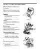
Operator’s Manual 500 series Snowthrower Model 6ML Shown IMPORTANT: Read safety rules and instructions carefully before operating equipment. CUB CADET, 60 OTTAWA STREET SOUTH, KITCHENER, ONTARIO N2G 3S7 Printed in U.S.A. FORM NO.
TABLE OF CONTENTS Content Customer Support Important Safe Operation Practices Setting Up Your SnowThrower Operating Your Snow Thrower Maintaining Your Snow Thrower Page 2 3 5 8 12 Content Service & Ajustments Off Season Storage Trouble Shooting Warranty Illustrated Parts List Page 13 17 18 19 20 FINDING MODEL NUMBER This Operator’s Manual is an important part of your new snow thrower. It will help you to assemble, prepare and maintain the unit for best performance.
SECTION 1: IMPORTANT SAFE OPERATION PRACTICES WARNING: This symbol points out important safety instructions which, if not followed, could endanger the personal safety and/or property of yourself and others. Read and follow all instructions in this manual before attempting to operate this machine. Failure to comply with these instructions may result in personal injury. When you see this symbol—heed its warning.
6. 7. 8. 9. 10. 11. 12. 13. 14. 15. 16. 17. 18. 19. 20. Maintenance And Storage odorless and deadly gas. Do not operate machine while under the influence of alcohol or drugs. Muffler and engine become hot and can cause a burn. Do not touch. Exercise extreme caution when operating on or crossing gravel surfaces. Stay alert for hidden hazards or traffic. Exercise caution when changing direction and while operating on slopes.
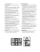
SECTION 2: SETTING UP YOUR SNOW THROWER NOTE: The snow thrower is shipped with oil and WITHOUT GASOLINE. After assembly, refer to separate engine manual for proper fuel and engine oil recommendations. NOTE: This Operator’s Manual covers several models, handle panels, lights and chute cranks are some features that may vary by model. Not all features referenced in this manual are applicable to all snowthrower models.
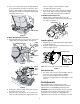
chute assembly as shown in Figure 6, cables should be towards the operator. 4. Insert the clevis pin, earlier removed, through the holes on the chute control box and chute support tube. Secure with the hairpin clip. See Figure 5. 3. One end of each chute keeper is already attached to the chute flange. Pivot the free end of the chute keeper to align it with the chute flange and push it till it snaps into position. See Figure 4. Repeat with remaining chute keepers. For All Models without Engine Covers 1.
Auger Control Test 8. If the wheels can still be turned when you engage the drive control, loosen the hex jam nut and rotate the coupling end of the cable (without turning the cable) in one turn. Recheck the adjustment and repeat if needed. 9. Tighten the jam nut to secure the cable when correct adjustment is reached. 1. To check the adjustment of the auger control, push forward the left hand control until the rubber bumper is compressed. There should be slack in the cable. 2. Release the control.
Tire Pressure (Pneumatic Tires) 1. Adjust skid shoes by loosening the four hex nuts (two on each side) and carriage bolts. Move skid shoes to desired position. 2. Make certain the entire bottom surface of skid shoe is against the ground to avoid uneven wear on the skid shoes. Retighten nuts and bolts securely. 3. Retighten the hex jam nut and repeat all three tests to verify proper adjustment has been achieved. The tires are over-inflated for shipping purposes. Check tire pressure and reduce to 15-20 psi.
IMPORTANT: Always release the drive control before changing speeds. WARNING: Never use your hand to clear a clogged discharge chute. Shut off engine and remain behind handles until all moving parts have stopped before unclogging. Auger Control The auger control is located on the left handle. Squeeze the auger control to engage the augers. Release to stop the snow throwing action. The drive control must also be released in order to stop the auger.
• • hole, grounded 120 volt A.C. receptacle. 10. Push down on the starter button until the engine starts. Do not crank for more than 10 seconds at a time. This electric starter is thermally protected. If overheated, it will stop automatically and can be restarted only when it has cooled to a safe temperature (a wait of 5 -10 minutes is required). 11. When the engine starts, release the starter button and slowly rotate the choke to OFF position.
NOTE: This same lever also locks auger control so you can turn the chute crank without interrupting the snow throwing process. against the starter. 3. If the engine still fails to start, repeat the first two steps. If continued attempts do not free starter, follow the electric starter procedures to start. 4. Avoid freezing of the recoil starter by referring to instructions below. 3.
• • the rear of the auger housing and restart engine. 6. While standing in the operator’s position (behind the snow thrower), engage the auger clutch lever for a few seconds to clear any remaining snow or ice from the discharge chute before continuing to clear snow. If for some reason, you have to operate the snow thrower on gravel, keep the skid shoe in the highest position for maximum clearance between ground and shave plate. Clean the snow thrower thoroughly after each use.
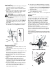
worn out belts. Replace, if necessary, following instructions on page 14. Lubricate pivot points Check Friction Wheel Follow instructions below to check the condition of the friction wheel rubber every 50 hours of operation. 1. Remove two self-tapping screws from the frame cover underneath the snow thrower. Refer to Figure 18. 2. Visually inspect the friction wheel rubber for excessive wear, cracks, or loose fit on the friction wheel drive hub. 3.
Shave Plate and Skid Shoes A The shave plate and skid shoes on the bottom of the snow thrower are subject to wear. Check these periodically and replace as necessary. Self-Tapping Screw Self-Tapping Screw Replacing Skid Shoe Belt Cover 1. Remove four carriage bolts and hex nuts which attach two skid shoes to the snow thrower on two sides. See Figure 16 . 2. Reassemble new skid shoes with the same hardware. Make certain the skid shoes are adjusted to be level. B Engine Pulley Replacing Shave Plate 1.
crank shaft, then working it around the groove of the drive pulley and finally wrapping it around the engine pulley from where the old belt was removed. Once the belt is firmly placed on the pulleys, make sure to remove the screwdriver from the idler. 9. Re-install auger belt on the engine pulley. 10. Re-attach frame cover on the snow thrower frame and put the equipment back to operating position. Re-attach belt cover with two self-tapping screws removed earlier. 9.
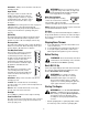
. Shift Arm Friction Wheel Hex Shaft Bearing Sprocket Figure 25 Figure 23 NOTE: If you placed plastic under the gas cap, be certain to remove it. Adjustments Plate Friction Wheel Drive Clutch Screw Refer to the Final Adjustment section of the Assembly instructions to adjust the drive clutch. To check the adjustment, proceed as follows: • Drain the gasoline out of your snow thrower’s engine, and place a piece of plastic film under the gas cap to avoid spillage.
Skid Shoe See Figure 26C. 4. Thread the ferrule up or down the shift rod as necessary until the ferrule lines up with the upper hole in the shift lever. See Figure 26B. 5. Insert ferrule into the upper hole in shift lever as shown in Figure 26B. 6. Reinstall the hairpin clip. 7. Check for correct adjustment before operating the snow thrower. B A Shift Refer to page 7 for details.
SECTION 7: TROUBLESHOOTING Problem Cause Remedy Engine fails to start. 1. 2. 3. 4. 5. 6. 7. Fuel tank empty, or stale fuel. Blocked fuel line. Choke not in ON position Faulty spark plug. Safety key not in ignition switch on engine. Spark plug wire disconnected. Primer button not being used properly. Engine runs erratic. 1. Unit running on CHOKE. 2. Blocked fuel line or stale fuel. 3. Water or dirt in fuel system. 4. Carburetor out of adjustment. 1. 2. 3. 4. 5. 6. 7. Fill tank with fresh gasoline.
SECTION 8: THREE (3) YEAR LIMITED WARRANTY For three (3) years from the date of original purchase of our products, we will either repair or replace, at its option, free of charge, F.O.B. Factory or authorized service firm, any part found to be DEFECTIVE IN MATERIAL and WORKMANSHIP for the original purchaser. all transportation charges on parts submitted for replacement under this warranty must be paid by the purchaser unless return is requested by the manufacturer.