
Assembly Instructions

7
ASSEMBLY & INSTALLATION
4. Once aligned, tighten all of the hardware installed at this time.
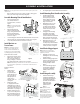
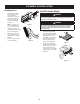
Install Mounting Plate/Strut Bracket Assembly
1. Install mounting plate/strut
bracket assembly onto lower
bracket previously attached to
frame by aligning interior holes
on struts with holes on upright
flanges of lower bracket.
2. Working from inside-out, secure
mounting plate/strut bracket
assembly to lower bracket with
two hex head screws (710-1238)
and two lock nuts (712-04063).
See (1) in Figure 7.
3. Swing upper arms of mounting
plate/strut bracket assembly
toward tractor frame, aligning
outside slots with holes on downward
flanges of keeper bracket previously
attached to frame. See (2) in Figure 7.
4. Working from outside-in, secure
mounting plate/strut bracket
assembly to keeper bracket with two
hex head screws (710-1238) and two
lock nuts (712-04063). See Figure 8.
Install Vertical Bagger Support
NOTE: This manual covers various bagger
configurations. Please follow the instructions
applicable to your machine.
1. Using Figure 9, locate the correct
mounting hole location on the mounting
plate for your tractor.
2. Install the vertical bagger support (683-
04519C) onto the mounting assembly on
the tractor by hooking it over the
mounting assembly, as shown in
Figure 10.
3. Secure the vertical bagger support
to the mounting assembly using
a hex bolt (710-06154B) from
hardware pack 689-02619. See
Figure 10.
Install Hanger Assembly
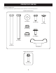
1. Install and secure the hanger
assembly (683-04498B) onto the
vertical bagger support using three
carriage bolts (710-0276), three
cup washers (736-0242) and three
flange lock nuts (712-
04063) from hardware
pack 689-02619. See
Figure 11.
NOTE: Cup washers should be
placed on same side as flange lock
nuts (towards frame).
NOTE: The carriage bolts (710-
0276), from hardware pack 689-
02619, go in the top holes with the
nuts facing the engine. The hex bolt
(710-1238), from the same hardware
pack, goes in the bottom hole.
Figure 7
Figure 8
4848
””
5454
””
6060
””
Figure 9
Figure 10
Figure 11
Figure 12
Figure 13
Figure 14
Figure 15
Figure 16
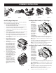
Install Top Bagger Components
With the mounting brackets assembled and in place on the tractor, follow these
steps to assemble the remaining bagger components.
1.
If not already installed by the factory, snap the vent cover into the
holes found on the chute support assembly.
2. Snap the upper chute support (731-17272) in place by first clipping the side
portion onto the hanger assembly rail (1) as shown in Figure 12.
3. Snap the front side of the upper chute support to the hanger assembly rail
(2) as shown in Figure 12.
4. Attach the deflector (731-18471) to the upper chute support using the three
(3) screws supplied in hardware pack 689-02299. See Figure 13.
5. If not already installed by the factory, install the bagger screen (731-06504)
into the bagger cover (631-06539) by first inserting one end into the
corresponding cutout mounting hole. Make sure to feed screen under lip, as
shown in Figure 14.
6. Install the bagger cover onto the
hanger assembly, as seen in Figure
15. The cover goes inside the two
mounting tabs.
7. Slide the hinge pin (711-05079) into
the hole located on the mounting
tab, as shown in Figure 16. Use
the cut-out windows (see inset
in Figure 16) to line up the hinge
pin on the other side and push
pin all the way in until it reaches
the end-stop. At this point the pin
clips into place and is secured by a
tab in the bagger cover.
8. Open hood by pushing in on the
rear, right-side tab with your right
hand (1), and lifting the cover
with your left hand in the center
rear of the bagger cover (2) as
shown in Figure 17.
9. Install all three bag assemblies
(664-05104) onto the hanger
assembly by inserting the front
edge in first (1), and then setting
the back edge down until it fits
into the assembly (2), as shown in
Figure 18.
Installing the Boot Assembly - 48” Triple Bagger
1. With the tractor’s
outer and inner
discharge chutes
raised up and held
open (1), install the
boot assembly (819-
011300) by placing
the hole on the boot
assembly bracket on
the tab located on
the top, right rear
of the deck (2), as
shown in Figure 19.
2. Pivot the boot
assembly forward,
sliding under the discharge chutes raised in Step 2, until the pin on the boot
assembly bracket aligns with the slot on the deck. See (3) in Figure 19.
NOTE: You should hear a click when the center tab on the boot assembly bracket snaps into
place on the deck.
3. Secure the boot assembly to the cutting deck using wing knob (720-04122)
from hardware pack 689-02619. See inset of Figure 19.
NOTE: The inner and outer spring-loaded discharge chutes will remain propped on the boot
assembly bracket, creating a seal between the deck and the boot assembly.
Installing the Boot Assembly - 54”/60” Triple Bagger
1. Raise the deck to its
highest position.
2. With the tractor’s
outer and inner
discharge chutes
raised up and held
open (1), install the
boot assembly (819-
011280) by placing
the hole on the boot
assembly bracket on
the tab located on
the top, right rear
of the deck (2), as
shown in Figure 20.
3. Pivot the boot assembly forward, sliding under the discharge chutes raised in
Step 2, until the pin on the boot assembly bracket aligns with the slot on the
deck. See (3) in Figure 20.
NOTE: You should hear a click when the center tab on the boot assembly bracket snaps into
place on the deck.
4. Secure the boot assembly to the cutting deck using wing knob (720-04122)
from hardware pack 689-02619. See inset of Figure 20.
NOTE: The inner and outer spring-loaded discharge chutes will remain propped on the boot
assembly bracket, creating a seal between the deck and the boot assembly.
Figure 17
Figure 18
2
3
1
Figure 19
2
3
1
Figure 20