
Installation Guide

Optional Kit 490-900-C066 5 of 9 Form No. 769-10822 /00
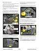
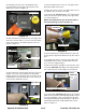
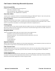
28. Carefully peel/remove the existing maintenance
meter label away from the upper dash and top of the
maintenance meter. See Figure 12.
FIGURE 12
Remove Label
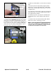
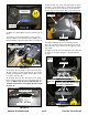
29. Reach inside the opening in the top of the upper dash
and remove the wire harness connector from the mainte-
nance meter. Depress the tab then pull the connector
down See Figure 13.
FIGURE 13
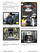
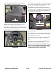
30. Reach inside the opening again and squeeze the two
(2) tabs on the sides of the maintenance meter while
pushing up and out of the upper dash. See Figure 14. A
small flat blade screw driver may be used to assist in the
removal of the maintenance meter.
Upper Dash
31. Push the maintenance meter out of the upper dash.
Discard the maintenance meter.
32. Make sure the top surface of the upper dash is free of
the old label, dirt, etc. Clean as needed.
33. Install Item #1 (725-06221) Bluetooth
®
enabled main-
tenance meter in the square opening of the upper dash
as shown In Figure 15.
NOTE: The terminal block must be at the bottom of
the square opening as shown in Figure 15.
34. Push the Bluetooth
®
enabled maintenance meter all
the way into the upper dash until the two (2) tabs snap in
place.
35. Install the wire harness connector to the Bluetooth
®
enabled maintenance meter. Confirm that the wire har-
ness connector snapped in place.
36. Remove the black rectangular section from the center
of Item #2 (777I25270) Rider Bluetooth
®
enabled mainte-
nance meter label as shown in Figure 16 and discard.
Wire Harness
Connector
Depress Tab
Tab
FIGURE 14
37. Install Item #2 (777I25270) Rider Bluetooth
®
enabled
maintenance meter label. Carefully align the label so that
the open rectangular section is centered over the silver
rectangular LCD display and parallel with the edge above
and below the Bluetooth
®
enabled maintenance meter
label. See Figure 17.
Upper Dash
Opening
Terminal Block
Item #1
(725-06221)
FIGURE 15
FIGURE 16
Item #2
(777I25270)
Remove Rectangular Section