
Installation Guide
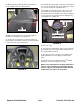

13. Make sure all air bubbles are removed from under the
label.
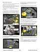
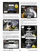
14. Reach up inside the right hand pod and install the
wire harness connector to the Bluetooth
®
enabled main-
tenance meter. Confirm that the wire harness connector
snapped in place.
15. Connect the positive battery cable to the positive bat-
tery terminal, then connect the negative battery cable to
the negative battery terminal.
16. Turn the key to the on position, the new Bluetooth
®
enabled maintenance meter display should show the
hours.
17. Start the rider and confirm the Bluetooth
®
enabled
maintenance meter is functioning correctly.
NOTE: Connect the Bluetooth
®
enabled maintenance
meter to your smartphone by downloading the Cub
Connect
™ App for your Bluetooth
®
capable Android
or iOS device. See Page 9 for instructions.
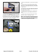
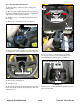
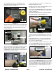
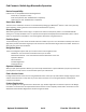
12. Install Item #3 (777I25406) RZT Bluetooth
®
enabled
maintenance meter label. Carefully align the label over
the maintenance meter so that the open rectangular sec-
tion is centered over the silver rectangular LCD display
and the left side of the label is aligned with the edge of
the throttle /choke control slot. See Figure 7.
Optional Kit 490-900-C066 3 of 9 Form No. 769-10822 /00
FIGURE 7
Item #3
(777I25406)
FIGURE 6
Remove Rectangular Section
Item #3
(777I25406)