For Discount Cub Cadet Parts Call 606-678-9623 or 606-561-4983 Professional Shop Manual RZT-S NOTE: These materials are for use by trained technicians who are experienced in the service and repair of outdoor power equipment of the kind described in this publication, and are not intended for use by untrained or inexperienced individuals. These materials are intended to provide supplemental information to assist the trained technician.
For Discount Cub Cadet Parts Call 606-678-9623 or 606-561-4983 www.mymowerparts.
For Discount Cub Cadet Parts Call 606-678-9623 or 606-561-4983 Table of Contents Chapter 1: Introduction Professional Shop Manual intent . . . . . . . . . . . . . . . . . . . . . . . . . . . . . . . . . . . 1 Fasteners . . . . . . . . . . . . . . . . . . . . . . . . . . . . . . . . . . . . . . . . . . . . . . . . . . . . . 1 Assembly . . . . . . . . . . . . . . . . . . . . . . . . . . . . . . . . . . . . . . . . . . . . . . . . . . . . . 3 Description of the RZT-S . . . . . . . . . . . . . . . . . . . . .
For Discount Cub Cadet Parts Call 606-678-9623 or 606-561-4983 Chapter 6: electrical system Introduction . . . . . . . . . . . . . . . . . . . . . . . . . . . . . . . . . . . . . . . . . . . . . . . . . . . 61 PTO Switch . . . . . . . . . . . . . . . . . . . . . . . . . . . . . . . . . . . . . . . . . . . . . . . . . . 63 Brake Switch . . . . . . . . . . . . . . . . . . . . . . . . . . . . . . . . . . . . . . . . . . . . . . . . . . 63 Reverse Safety Switch . . . . . . . . . . . . . . . . . . . . . . . . .
For Discount Cub Cadet Parts Call 606-678-9623 or 606-561-4983 Diodes . . . . . . . . . . . . . . . . . . . . . . . . . . . . . . . . . . . . . . . . . . . . . . . . . . . . . . 99 Relay . . . . . . . . . . . . . . . . . . . . . . . . . . . . . . . . . . . . . . . . . . . . . . . . . . . . . . . 101 Schematic . . . . . . . . . . . . . . . . . . . . . . . . . . . . . . . . . . . . . . . . . . . . . . . . . . . 102 Chapter 7: Decks and lift shaft Cutting decks . . . . . . . . . . . . . . . . . . . . . . . .
For Discount Cub Cadet Parts Call 606-678-9623 or 606-561-4983 IV www.mymowerparts.
For Discount Cub Cadet Parts Call 606-678-9623 or 606-561-4983 Introduction CHAPTER 1: INTRODUCTION Professional Shop Manual intent This Manual is intended to provide service dealers with an introduction to the mechanical aspects of the RZT-S zero-turn mower. • Detailed service information about the engine will be provided by the engine manufacturer, in most cases. Disclaimer: The information contained in this manual is correct at the time of writing.
For Discount Cub Cadet Parts Call 606-678-9623 or 606-561-4983 RZT-S • Be prepared in case of emergency: ! CAUTION Keep a fire extinguisher nearby Keep a first aid kit nearby Keep emergency contact numbers handy • Replace any missing or damaged safety labels on shop equipment. • Replace any missing or damaged safety labels on equipment being serviced. • Grooming and attire: ! WARNING Do not wear loose fitting clothing that may become entangled in equipment.
For Discount Cub Cadet Parts Call 606-678-9623 or 606-561-4983 Introduction Assembly Torque specifications may be noted in the part of the text that covers assembly, they may also be summarized in tables along with special instructions regarding locking or lubrication. Whichever method is more appropriate will be used. In many cases, both will be used so that the manual is handy as a quick-reference guide as well as a step-bystep procedure guide that does not require the user to hunt for information.
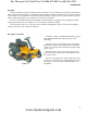
For Discount Cub Cadet Parts Call 606-678-9623 or 606-561-4983 RZT-S Model and Serial Numbers The model and serial number tag can be found under the seat. See Figure 1.2. The serial number is located to the right of the model number as shown above. See Figure 1.2. Figure 1.2 The model number is 17WF2BDS055. The break down of what the number mean is as follows: 1 .............................................................................................. Residential machine ....7 .......................
For Discount Cub Cadet Parts Call 606-678-9623 or 606-561-4983 Engine Related Parts CHAPTER 2: ENGINE RELATED PARTS This chapter will cover the engine accessories that are manufactured by Cub Cadet. IMPORTANT: The engine is supplied by Kohler. Refer to the Kohler manual for engine specific service information. Muffler Remove the muffler by following these steps: Bumper 1. Remove the four screws (two on each side) that hold the rear bumper in place using a 1/2” wrench. See Figure 2.1. 2.
For Discount Cub Cadet Parts Call 606-678-9623 or 606-561-4983 RZT-S Fuel System Fuel tank removal/replacement Remove/replace the fuel tank by following these steps: Gasoline and its vapors are extremely flammable. Use common sense when working around the fuel system. ! CAUTION 1. Remove the left fender: 1a. Remove the two screws, indicated by the arrows in Figure 2.3, from the underside of the fender using a 3/8” wrench. NOTE: The left rear wheel was removed for a clear view of the screws. Figure 2.
For Discount Cub Cadet Parts Call 606-678-9623 or 606-561-4983 Engine Related Parts Screw 1c. Remove the screw from the front of the fender using a T-27 torx driver. See Figure 2.5. 1d. Unscrew the fuel cap. NOTE: The fuel cap is tethered to the fender. This is an EPA tier III requirement. 1e. Lift the fender off of the mower. Figure 2.5 Fuel line Vent hose Roll over valve 2. Clamp off the fuel line between the fuel tank and the fuel filter. See Figure 2.6. 3.
For Discount Cub Cadet Parts Call 606-678-9623 or 606-561-4983 RZT-S Fuel pick up tube The fuel tank on the RZT-S mower has a fuel pick up tube. This is a rigid tube that runs from the bottom of the tank to the top of the tank were the fuel line attaches to it. NOTE: A loose or missing pick up tube will allow air into the fuel system and will reduce or prevent fuel follow from the fuel tank to the engine. To remove/replace the pick up tube: 1.
For Discount Cub Cadet Parts Call 606-678-9623 or 606-561-4983 Engine Related Parts Fitting 6. Inspect the pick up tube. See Figure 2.9. NOTE: If the pick up tube is loose or missing, it must be replaced. 7. Install the grommet in the fuel tank. 8. Insert the pick up tube into the fuel tank, through the grommet. 9. Re-connect the fuel line. 10. Install the left fender. Grommet pick up tube 11. Test run the mower in a safe area before returning it to service. Figure 2.
For Discount Cub Cadet Parts Call 606-678-9623 or 606-561-4983 RZT-S Evaporative (EVAP) emissions system The EPA has enacted rules that regulate the amount of vapors an engine’s fuel system is allowed to vent to the atmosphere. The rules are know as tier III emissions guidelines. These rules apply to all engines built on or after 1/1/ 2012. Some of the requirements of tier III emissions include: • Tethered fuel caps. • Unvented fuel caps.
For Discount Cub Cadet Parts Call 606-678-9623 or 606-561-4983 Engine Related Parts Troubleshooting Symptom Engine starts, then dies Cause A blockage in the vent hose. The roll over valve is stuck closed. Engine runs rich Raw gasoline in the charcoal canister (if equipped). A blockage in the line between the charcoal canister (if equipped) and the intake manifold. Engine runs lean Wrong fuel cap installed. Leak in the vacuum lines.
For Discount Cub Cadet Parts Call 606-678-9623 or 606-561-4983 RZT-S Roll over valve vent To remove the roll over valve: 1. Remove the left fender by following the procedures described in Chapter 3: Body. 2. Disconnect the vent hose. See Figure 2.13. Vent hose NOTE: The vent hose will have a red trace. Red trace Figure 2.13 3. 4. Gently pry the roll over valve out of the fuel tank. See Figure 2.14. Roll over valve Inspect the rubber grommet, replace if damaged. To install the roll over valve: 1.
For Discount Cub Cadet Parts Call 606-678-9623 or 606-561-4983 Engine Related Parts Testing the roll over valve The roll over valve vent has two functions. The first function is to vent the tank and the second function is to close off the vent if the tank is inverted. 15 in.Hg. Test the roll over valve by: 1. Remove the roll over valve by following the steps previously described in this section. 2. Connect a vacuum pump to the roll over valve. 3. Hold the roll over valve in an inverted position. 4.
For Discount Cub Cadet Parts Call 606-678-9623 or 606-561-4983 RZT-S Control cable adjustment To adjust the control cable: 1. Move the throttle lever to the detent between the full throttle and the choke position. 2. Loosen the clamp that holds the control cable jacket in position. See Figure 2.17. 3. Slide the cable jacket until the speed control lever makes contact with the choke lever. 4. Tighten the control cable jacket. 5. Move the throttle lever to the choke position. 6.
For Discount Cub Cadet Parts Call 606-678-9623 or 606-561-4983 Body CHAPTER 3: BODY Floor pan To remove/replace the floor pan: 1. Remove the steering wheel: 1a. Turn the steering wheel so that the wheels are pointing straight ahead. 1b. Gently pry the cover off of the steering wheel. 1c. Remove the screw and washer that secures the steering wheel to the steering shaft using a 1/2” wrench. See Figure 3.1. 1d. Lift the steering wheel off of the steering shaft. Screw Figure 3.1 2.
For Discount Cub Cadet Parts Call 606-678-9623 or 606-561-4983 Z-Force-S 3. Remove the reverse pedal using a pair of 7/16” wrenches. See Figure 3.3. Reverse pedal Figure 3.3 4. Remove the forward drive pedal: See Figure 3.4. 4a. 4b. Remove the screw that secures the drive pedal to the pedal shaft bell crank using a 1/2” wrench. Forward drive pedal Unhook the drive pedal from the bell crank. Figure 3.4 5.
For Discount Cub Cadet Parts Call 606-678-9623 or 606-561-4983 Body Left fender To remove/replace the left fender: NOTE: The fuel tank is nested inside the left fender. Gasoline and its vapors are extremely flammable. Use common sense when working around the fuel system. ! CAUTION 1. Remove the two screws, indicated by the arrows in Figure 3.6, from the underside of the fender using a 3/8” wrench. NOTE: The left rear wheel was removed for a clear view of the screws. Figure 3.6 2.
For Discount Cub Cadet Parts Call 606-678-9623 or 606-561-4983 Z-Force-S Right fender To remove/replace the right fender: 1. Remove the yellow throttle lever using a #1 phillips screwdriver. See Figure 3.9. 2. Disconnect the throttle lever assembly from the right fender using a T-30 torx driver. See Figure 3.9. Figure 3.9 3. Remove the two screws, indicated by the arrows in Figure 3.10, from the inboard side of the fender using a T-27 torx driver. Figure 3.10 4.
For Discount Cub Cadet Parts Call 606-678-9623 or 606-561-4983 Body Hour meter Key switch 6. Disconnect the key switch. See Figure 3.12. 7. Disconnect the hour meter. 8. Disconnect the PTO switch. 9. Remove the two screws from the underside of the right fender using a 3/8” wrench. See Figure 3.13. PTO switch Figure 3.12 10. Lift the fender off of the mower. 11. Install the fender by following the previous steps in reverse order. 12.
For Discount Cub Cadet Parts Call 606-678-9623 or 606-561-4983 Z-Force-S Seat box assembly To remove/replace the seat box assembly: 1. Remove the battery. 2. Remove the deck by following the procedures described in Chapter 7: Decks and Lift Shaft. 3. Remove the left fender by following the procedures described in the left fender section of this chapter. 4. Remove the right fender by following the procedures described in the right fender section of this chapter 5.
For Discount Cub Cadet Parts Call 606-678-9623 or 606-561-4983 Body 10. Remove the four screws (two on each side), securing the seat box to the cross member using a 1/2” wrench. See Figure 3.17. Screws Figure 3.17 Cross member screw 11. Seat box screws Remove the four screws (two on each side), that hold the seat box to the frame using a 1/2” wrench. See Figure 3.18. 12. Remove the two screws (one on each side), that hold the cross member to the frame NOTE: The cross member can be left in place.
For Discount Cub Cadet Parts Call 606-678-9623 or 606-561-4983 Z-Force-S 22 www.mymowerparts.
For Discount Cub Cadet Parts Call 606-678-9623 or 606-561-4983 Brakes and Drive System CHAPTER 4: BRAKE AND DRIVE SYSTEM Brake system description The RZT-S uses twin EZT Hydro-Gear transmissions to drive the rear wheels. The hydraulic action of the transmissions will provide the braking for the mower while it is in motion. There is a friction brake on the transmission that is used as a parking brake. • There is a brake for each transmission.
For Discount Cub Cadet Parts Call 606-678-9623 or 606-561-4983 RZT-S Brake adjustment NOTE: When performing a brake adjustment, inspect the brake components for signs of wear or damage. 1. Block the front wheels. 2. Lift and safely support the rear of the mower. NOTE: Make sure the parking brake is released. 3. Remove the cotter pin locking the castle nut on the brake caliper. See Figure 4.3. 4. Back the castle nut off a few turns using a 9/16” wrench.
For Discount Cub Cadet Parts Call 606-678-9623 or 606-561-4983 Brakes and Drive System Brake puck/rotor replacement On Hydro-Gear transmissions, the brake pucks are wearing parts that will need to be serviced from time to time. If a mower is operated with the parking brake dragging, the pucks will wear out rapidly and the brake rotor will develop hot spots. If the mower is operated long enough, the rotor may have grinding marks on it with excessively worn pucks.
For Discount Cub Cadet Parts Call 606-678-9623 or 606-561-4983 RZT-S 6. Remove the front mounting bolt, allowing the caliper to swing down. See Figure 4.7. 7. The outboard brake puck should fall out when the brake caliper swings down. If it did not, it can be removed now. Caliper Figure 4.7 8. Slide the brake rotor off to reach the inboard brake puck. See Figure 4.8. 9. Remove the caliper for inspection when servicing the brake pucks. To do this, remove the rear bolt loosened in step 4.
For Discount Cub Cadet Parts Call 606-678-9623 or 606-561-4983 Brakes and Drive System 14. Place a new puck into the caliper. See Figure 4.10. NOTE: A piece of scotch tape may be used to hold the new brake pucks in place for assembly. The tape will grind away when the brakes are applied. 15. Place a new brake puck into the recess in the transmission. Use a piece of scotch tape to hold it in place. 16. Slide the brake rotor in place, shoulder out. Puck held in place with tape Figure 4.10 17.
For Discount Cub Cadet Parts Call 606-678-9623 or 606-561-4983 RZT-S Brake shaft Bushings NOTE: The brake shaft is captive on the deck lift shaft. It is serviced with the deck lift shaft. Refer to the deck lift shaft section of Chapter 7: Decks and Lift Shaft for removal/replacement procedures. To replace the brake shaft bushings: 1. Remove the battery. 2. Remove the deck by following the procedures described in Chapter 7: Decks and Lift Shaft. 3.
For Discount Cub Cadet Parts Call 606-678-9623 or 606-561-4983 Brakes and Drive System Brake shaft 9. Remove the split spacer from the right side of the deck lift shaft. See Figure 4.13. Split spacer Deck lift shaft Figure 4.13 10. Slide the right split bushing out of the brake shaft until it is full exposed. See Figure 4.14. Split bushing NOTE: Sliding the brake shaft to the left can help slide the bushing out of the brake shaft. 11. Remove the split bushing. 12. Install a new bushing. 13.
For Discount Cub Cadet Parts Call 606-678-9623 or 606-561-4983 RZT-S Drive belt To remove/replace the drive belt: NOTE: If a drive belt fails prematurely, find and correct the cause of the failure. 1. Remove the deck as described in Chapter 7: Cutting Decks and Lift Shaft. 2. Lift and safely support the rear of the mower. 3. Remove the battery. See Figure 4.16. Battery Figure 4.16 4. Remove the nuts that hold the right belt guard to the frame using a 7/16” wrench. See Figure 4.17. 5.
For Discount Cub Cadet Parts Call 606-678-9623 or 606-561-4983 Brakes and Drive System PTO Harness Belt guard 8. Remove the rear belt guard using a 3/8” wrench. See Figure 4.19. 9. Disconnect the harness from the PTO clutch Figure 4.19 10. Disconnect the brake de-clutching rod from the idler pulley bracket. See Figure 4.20. 11. Remove the idler pulley tensioning spring. 12. Loosen the bolt the idler pulley spins on enough to allow the belt to slip between the pulley and the belt guide. See Figure 4.
For Discount Cub Cadet Parts Call 606-678-9623 or 606-561-4983 RZT-S Drive belt adjustment The drive belt is tensioned by a spring loaded idler pulley. When the brakes are applied, the drive belt is declutched. An adjustable linkage connects the tensioning pulley to the brake shaft. A brake link that is out of adjustment will prevent the moveable idler from correctly tensioning and de-tensioning the belt. As the belt wears, the moveable idler needs to push the belt in further to keep proper belt tension.
For Discount Cub Cadet Parts Call 606-678-9623 or 606-561-4983 Brakes and Drive System Transmission removal/replacement The Hydro-Gear shop manual for the EZT transmissions is form number BLN-52622. This manual is available through Hydro-Gear. Reasons to remove a transmission from an RZT-S mower: 1. To repair or replace the transmission 2. To change the transmission fluid Repair or replacement Before doing any work to the Hydro-Gear transmission in the RZT-S, refer to the Hydro-Gear Manual: BLN52622.
For Discount Cub Cadet Parts Call 606-678-9623 or 606-561-4983 RZT-S A loss of performance in one transmission can be caused by: 1. Rear tires with different circumference or rolling resistance. Air pressure in the rear tires is the most common cause of this condition. 2. A dragging brake. This will also cause drive system noise and it will create heat at the brake and in the transmission. 3. A partially engaged hydraulic relief rod on one transmission.
For Discount Cub Cadet Parts Call 606-678-9623 or 606-561-4983 Brakes and Drive System To remove/replace a transmission: 1. Remove the deck as described in Chapter 7: Cutting Decks and Lift Shaft. 2. Lift and safely support the rear of the mower. 3. Remove the idler pulley tensioning spring. See Figure 4.24. 4. Remove the wheel from the transmission being serviced using a 3/4” wrench. 5. Disconnect the secondary brake rod from the brake shaft bell crank by removing the bowtie clip. 6.
For Discount Cub Cadet Parts Call 606-678-9623 or 606-561-4983 RZT-S 8. Remove the nut and bolt that holds the front of the transmission to the mounting bracket using a pair of 1/2” wrenches. See Figure 4.27. Mounting bracket Figure 4.27 9. Remove the nut, T-bolt and spacer that connect the transmissions to each other using a 1/2” wrench and an 11/16” wrench. See Figure 4.28. Nut Spacer Figure 4.28 10.
For Discount Cub Cadet Parts Call 606-678-9623 or 606-561-4983 Brakes and Drive System 11. Bypass rod Remove the bowtie clip that secures the bypass rod to the by-pass arm. See Figure 4.30. 12. Slide the bypass rod off of the bypass arm. Figure 4.30 Transmission bolts 13. Support the transmission to prevent it from falling while the mounting bolts are removed. 14. Remove the two bolts that fasten the transmission to the frame. See Figure 4.31. 15.
For Discount Cub Cadet Parts Call 606-678-9623 or 606-561-4983 RZT-S Hydro neutral control adjustment NOTE: Neutral control rarely goes out of adjustment on its own. If it needs adjustment, check for damaged linkage or signs of tampering. ! CAUTION The mower engine and drive system must be operated to complete this procedure. Confirm that no hazards will be incurred by running the engine or operating the drive system. • Work in a well vented area to prevent carbon monoxide poisoning or asphyxiation.
For Discount Cub Cadet Parts Call 606-678-9623 or 606-561-4983 Brakes and Drive System 3. Disconnect both of the drive control rods from the transmission control arms using a pair of 9/16” wrenches. See Figure 4.34. 4. Start the engine and advance throttle to maximum RPM. 5. Release the parking brake. 6. Observe the movement of both rear wheels. See Figure 4.35. Drive control rods Figure 4.
For Discount Cub Cadet Parts Call 606-678-9623 or 606-561-4983 RZT-S Socket head cap screw 7. With the engine still running, locate the socket head cap screw in the slot of the transmission control arm on the transmission that needs to be adjusted. 8. Loosen the socket head cap screw using a 1/4” hex key. See Figure 4.36. 9. Adjust the transmission control arm(s) until the wheel(s) stops moving. 10. Tighten the socket head cap screw using a 1/4” hex key. 11. Turn the engine off. 12.
For Discount Cub Cadet Parts Call 606-678-9623 or 606-561-4983 Brakes and Drive System Control pedal shaft assembly Steering shaft bolt NOTE: The control pedal shaft is an assembly of the brake pedal shaft and the drive pedal shaft. To remove/replace the control pedal shaft assembly: 1. Remove the floor board by following the procedures described in Chapter 3: Body. 2. Install the alignment fixtures and pins by following the procedures described in Chapter 5: Steering. 3.
For Discount Cub Cadet Parts Call 606-678-9623 or 606-561-4983 RZT-S 8. Remove the two nuts and bolts that hold the front of the steering column assembly to the mower using a pair of 1/2” wrenches. See Figure 4.40. Bolts Figure 4.40 9. Remove the two screws that hold the rear of the steering column assembly to the mower using a 1/2” wrench. See Figure 4.41. 10. Lift the steering column assembly off of the mower. Screws Figure 4.41 11.
For Discount Cub Cadet Parts Call 606-678-9623 or 606-561-4983 Brakes and Drive System 12. Remove the bolt that is pressing against the left control pedal shaft bracket and its nut using a pair of 9/ 16” wrenches. See Figure 4.43. Bolt NOTE: This bolt is used to limit the side to side movement of the control pedal shaft assembly. If the mowers was built prior to March 22, 2012 or has a shorter bolt that does not press against the control pedal bracket, replace it with a 3/8-16 x 2.
For Discount Cub Cadet Parts Call 606-678-9623 or 606-561-4983 RZT-S 16. Disconnect the reverse switch. 17. Remove the two screws that hold the right control pedal bracket to the frame using a 1/2” wrench. See Figure 4.46. 18. Lift the control pedal shaft assembly out of the mower. 19. Slide the left control bracket and bushing off of the pedal shaft. Screws Reverse switch Figure 4.46 20. Remove the bowtie clip that holds the right control bracket to the pedal shaft. See Figure 4.47. 21.
For Discount Cub Cadet Parts Call 606-678-9623 or 606-561-4983 Brakes and Drive System Timing marks 24. Make sure the pinion gear is installed so that the timing marks on the pinion gear line up with the timing marks on the sector gears. NOTE: The timing marks are there to align the gear with the bushing during installation of the steering column. They are not used for alignment adjustments. 25. Install the control pedal shaft by following steps 1 through 23 in reverse order. 26.
For Discount Cub Cadet Parts Call 606-678-9623 or 606-561-4983 RZT-S 46 www.mymowerparts.
For Discount Cub Cadet Parts Call 606-678-9623 or 606-561-4983 Steering CHAPTER 5: STEERING Introduction The steering on the RZT-S mower works in two phases. • First it steers like any other riding mower by turning the front wheels. • Second and more importantly, the steering linkage controls the drive output of the two Hydro-Gear transmissions. The steering shaft has a pinion gear that drives a pair of segment gears. When the steering wheel is turned, the segment gears turn the front wheels.
For Discount Cub Cadet Parts Call 606-678-9623 or 606-561-4983 RZT-S Wheel alignment and drive control link adjustments The wheel alignment and drive control link adjustments are performed together on the RZT-S. IMPORTANT: Check the tire air pressure and wear before attempting to diagnose any problems with the steering or tracking of a RZT-S riding mower. If the tire circumferences are not equal across the same axles, it will greatly affect the performance of the riding mower.
For Discount Cub Cadet Parts Call 606-678-9623 or 606-561-4983 Steering Alignment pin 8. Install the segment gear alignment pins (1/4”). See Figure 5.3. Figure 5.3 9. Insert the axle casting (5/16”) alignment pins into the alignment holes in both axle castings. See Figure 5.4. NOTE: There may be some variability in the size of the axle casting alignment holes. The taper of the 5/ 16” alignment pin will center the pin in the alignment hole. Alignment pin Figure 5.4 Holes aligned 10.
For Discount Cub Cadet Parts Call 606-678-9623 or 606-561-4983 RZT-S 13. Install the speed cam alignment bar. See Figure 5.6. Timing mark Timing mark Speed cam alignment bar Figure 5.6 14. Install the control link alignment fixture in the slots of the control links. See Figure 5.7. NOTE: Make sure the bolts in the cam slots are aligned with the speed cam timing marks. Control link alignment fixture Figure 5.7 15.
For Discount Cub Cadet Parts Call 606-678-9623 or 606-561-4983 Steering Front wheels Remove/ replace the front wheels: Axle bolt 1. Lift and safely support the front end of the riding mower. 2. Remove the axle bolt and nut using a pair of 3/4” wrenches. See Figure 5.9. Figure 5.9 3. Slide the tire and wheel assembly out of the yoke. NOTE: There is a short spacer on each side of the wheel. The short spacers slide over the long spacer that the axle bolt passes through. See Figure 5.10. Long spacer 4.
For Discount Cub Cadet Parts Call 606-678-9623 or 606-561-4983 RZT-S To replace the front wheel bearings: 1. Lift and safely support the front of the mower. 2. Remove the front wheel by following the procedures describe in the previous section of this chapter. 3. Drive the bearings out of the wheel hub using a drift or pin punch. See Figure 5.11. Punch Figure 5.11 4. Drive in the new bearings using a brass punch or a tube that has the same O.D. as the bearing. See Figure 5.12. 5.
For Discount Cub Cadet Parts Call 606-678-9623 or 606-561-4983 Steering Front yokes To remove/ replace the front yokes: Yoke cover 1 Lift and safely support the front of the mower. 2. Remove the front wheel by following the procedures in the front wheel section of this chapter. 3. Pry the yoke cover off. See Figure 5.13. 4. Align the hole of the inboard steering gear with the hole in the axle casting. Alignment hole Figure 5.13 5.
For Discount Cub Cadet Parts Call 606-678-9623 or 606-561-4983 RZT-S Removal of the steering gears To remove the steering gears: 1. Remove the floor pan, following the procedures described in Chapter 3: Body. 2. Remove the nut from the bolt that holds the drag link to the inboard steering gear using a pair of 9/16” wrenches. See Figure 5.16. Nut Inboard steering gear Figure 5.16 5/16” alignment pin 3. Remove the front yokes by following the procedures in the front yokes section of this chapter. 4.
For Discount Cub Cadet Parts Call 606-678-9623 or 606-561-4983 Steering NOTE: The same part number gear is used on both yokes. If the gear is to be used on the left yoke, install it so that the LH stamped into the gear is facing up. If the gear is to be used on the right yoke, install it so that the RH stamped into the gear is facing up. See Figure 5.19. 7. Slide the gear off of the yoke. Figure 5.19 Hex screw 8. Remove the hex screw that holds the steering gear to the shaft using a 9/16” wrench.
For Discount Cub Cadet Parts Call 606-678-9623 or 606-561-4983 RZT-S Installation and timing of the steering gears To install and time the steering gears: 1. 2. Install the alignment fixtures and alignment pins by following the procedures described in the wheel alignment and drive control link adjustments section of this chapter. “RH” facing up Slide the double-D of the steering gear shaft into the double-D hole of the inboard steering gear.
For Discount Cub Cadet Parts Call 606-678-9623 or 606-561-4983 Steering 11. Attach the drag link ball joint end to the inboard steering gear. Use a pair of 1/2” wrenches to tighten the nut and bolt. NOTE: If necessary, adjust the drag link ball joint end so that the hole in the ball joint end lines up with the hole in the steering gear. 12. Slide the yoke into the axle casting from the underside. NOTE: The flat side of the yoke should be parallel to the box section of the frame. See Figure 5.24. 13.
For Discount Cub Cadet Parts Call 606-678-9623 or 606-561-4983 RZT-S Drag links To remove/replace a drag link: 1. Remove the floor pan by following the procedures described in Chapter 3: Body. 2. Turn the steering wheel so that the drag links outer ball joint is accessible through the opening if the frame. See Figure 5.25. 3. Loosen the both the inner and outer drag link ball joint jam nuts using a 9/16” wrench. 4. Remove the outer ball joint using a pair of 9/16” wrenches.
For Discount Cub Cadet Parts Call 606-678-9623 or 606-561-4983 Steering 7. Remove the ball joint ends, counting the number of turns required to remove each ball joint. See Figure 5.27. 8. Remove the jam nuts. 9. Install the jam nuts on the new drag link. NOTE: Thread the jam nuts all the way to the unthreaded section of the drag link. 10. Install the ball joint ends. NOTE: The ball joints should be threaded on to the drag link the same number of turns as was required to remove them from the old drag link.
For Discount Cub Cadet Parts Call 606-678-9623 or 606-561-4983 RZT-S 60 www.mymowerparts.
For Discount Cub Cadet Parts Call 606-678-9623 or 606-561-4983 Electrical System CHAPTER 6: ELECTRICAL SYSTEM Introduction This chapter is divided into five sections: • Introduction: About this chapter and precautions • Components: This section will describe the location and operation of the electrical components on the mower. Where appropriate, some disassembly or component removal instructions will be included.
For Discount Cub Cadet Parts Call 606-678-9623 or 606-561-4983 RZT-S • Symptom: loud “BANG” when key is turned to the OFF position: The after fire solenoid is not closing, either because it is physically damaged or the power is not being turned off. Check for power at the solenoid. Check continuity between G and L terminals. Check for no continuity between L and the B terminals.
For Discount Cub Cadet Parts Call 606-678-9623 or 606-561-4983 Electrical System PTO Switch Understanding the PTO switch Figure 7.2 3. 1. A-COM is in the starter circuit. It is a Normally Closed (NC) set of contacts. Power coming from the brake switch (key switch in START, brakes ON) flows through the orange wire with black trace to the PTO switch.
For Discount Cub Cadet Parts Call 606-678-9623 or 606-561-4983 RZT-S Reverse Safety Switch The Reverse Safety Switch is mounted on the right brake pedal shaft support bracket. It is the same part number as the parking brake switch. It has two sets of contacts, but only the normally open (NO) set is used. See Figure 7.4. • When the reverse pedal is depressed, the reverse pedal bracket swings up and depresses the reverse switch plunger before it starts to move the control linkage.
For Discount Cub Cadet Parts Call 606-678-9623 or 606-561-4983 Electrical System Starter solenoid The starter solenoid is mounted to the rear frame cross member under the seat. See Figure 7.6. • When the proper safety conditions are met (brake applied and PTO OFF), the orange wire with white trace energizes the windings that magnetize an iron core, pulling the contacts closed between the two heavy posts, connecting battery power to the starter motor.
For Discount Cub Cadet Parts Call 606-678-9623 or 606-561-4983 RZT-S Start Circuit Turning the key to the START position: • spins the starter motor • enables the ignition - " • energizes the afterfire solenoid , ' 3 The circuit that sends power to the starter motor: See Figure 7.8. 1. 2. . # . / "RAKE 3WITCH $EPRESSED +EY 3WITCH 3YSTEM -ONITOR When the key switch is in the START position, battery power is passed from the “B” terminal to the “S” terminal.
For Discount Cub Cadet Parts Call 606-678-9623 or 606-561-4983 Electrical System Magneto Once the starter motor spins, it still needs spark and fuel to run. Looking at the circuits that do that: Magneto 1. The ignition sparks are generated by an ignition module. The ignition module will work as long as the primary windings are not grounded. With the key switch in any position other than OFF, there is no connection between the M (Module) terminal and the G (Ground) terminal. See Figure 7.9. 2.
For Discount Cub Cadet Parts Call 606-678-9623 or 606-561-4983 RZT-S 3. The L terminal on the key switch sends power to: • the Afterfire Solenoid • the windings of the PTO Relay • the PTO Switch C-COM terminal • the System Monitor 3 - " , ' &USE 'ROUND 3YSTEM -ONITOR See Figure 7.11. !FTERFIRE 3OLENOID 3TARTER 3OLENOID 04/ 3WITCH 'ROUND ! 04/ 2ELAY !T 2EST " # 'ROUND . # . / #/- 0/3 .%' 'RND "ATTERY Figure 7.11 68 www.mymowerparts.
For Discount Cub Cadet Parts Call 606-678-9623 or 606-561-4983 Electrical System Run Circuit With the key switch in the RUN position, the L terminal sends power to: 3 - " , ' &USE • the Afterfire Solenoid • the windings of the PTO Relay • the PTO Switch C-COM terminal 'ROUND 3YSTEM -ONITOR • the sYstem Monitor !FTERFIRE 3OLENOID 3TARTER 3OLENOID 04/ 3WITCH 'ROUND ! 04/ 2ELAY !T 2EST " 'ROUND See Figure 7.12.
For Discount Cub Cadet Parts Call 606-678-9623 or 606-561-4983 RZT-S Engine shut-down circuits Engine shutdown circuits stop the engine by disabling the ignition and removes power from the afterfire solenoid. .H\ 6ZLWFK 3 0DJQHWR Key switch shut-down: See Figure 7.13. The key switch turned to OFF connects the M (Module) terminal and L to G (Ground). • Grounding the magneto primary windings prevents the magneto from developing the magnetic field that it collapses to generate a spark.
For Discount Cub Cadet Parts Call 606-678-9623 or 606-561-4983 Electrical System Charging circuit How it works Stator 1. When the engine is running, magnets attached to the underside of the flywheel induce AC (Alternating Current) in the stator that is mounted beneath the flywheel. See Figure 7.15. 2. The AC travels from the stator to and from the regulator/rectifier through the two white wires. NOTE: The magnets inside the flywheel act as a rotor for the charging system.
For Discount Cub Cadet Parts Call 606-678-9623 or 606-561-4983 RZT-S .H\ 6ZLWFK 5. From the harness connector: See Figure 7.17. 5a. 5b. 5c. 3 The red/white trace wire leads to the 20A fuse. From the fuse, the wire connects to the starter solenoid, sharing the “hot” post with the battery cable. - " , ' *URXQG The shared post on the starter solenoid provides the final connection for the alternator output to reach the battery.
For Discount Cub Cadet Parts Call 606-678-9623 or 606-561-4983 Electrical System 4. System check, to identify the problem The system check consists of: • Stator check • Regulator Rectifier check • Downstream check 5. Figure 7.19 Stator check: See Figure 7.19. 5a. Key OFF, unplug the stator from the regulator rectifier. 5b. Check resistance through the stator using a digital multimeter set to read Ohms(Ω). • It should be between 0.1Ω and 0.14Ω. • A high reading indicates a fault in the windings.
For Discount Cub Cadet Parts Call 606-678-9623 or 606-561-4983 RZT-S 5d. 6. Interpretation: • If the stator fails either or both tests, it is likely to be bad. • If the stator fails the output test, but passes the resistance test, there is a possibility that the magnets on the rotor (flywheel) have lost their fields. This is theoretically possible, but extremely rare in practice. • It is necessary to remove the flywheel to test the magnets.
For Discount Cub Cadet Parts Call 606-678-9623 or 606-561-4983 Electrical System 7. If the regulator/rectifier fails any one of these tests, replace it with a new one. Test # Pos. Probe COM. Probe Results 1 Housing B+ O.L. (infinite resistance) 2 Housing AC 1 O.L. (infinite resistance) 3 Housing AC2 > 1.0 Ω (5 second delay) 4 B+ AC1 0 Ω (Perfect continuity) 5 B+ AC2 > 1.0 Ω 6 B+ Housing > 1.0 Ω 7 AC1 B+ 0 Ω (Perfect continuity) 8 AC1 AC2 > 1.0 Ω 9 AC1 Housing > 1.
For Discount Cub Cadet Parts Call 606-678-9623 or 606-561-4983 RZT-S PTO Circuit Basic Operation: See Figure 7.24. 1. 3. 3 - " , ' The PTO clutch gets power from the L terminal of the key switch through the C-NO terminal of the PTO switch when it is turned ON. The PTO clutch gets ground through the PTO relay COM terminal via the PTO relay NC terminal when the relay is not energized.
For Discount Cub Cadet Parts Call 606-678-9623 or 606-561-4983 Electrical System 3. 3 - " , ' 372 &OXWFK & 3a. The PTO clutch ground path that passes through the PTO relay is disconnected from the clutch. 3b. The ground path formerly used by the clutch is shifted to provide a second ground path for the relay windings. 3c. Once the relay windings have established the second ground path, the relay is latched on, even if the ground path that initially energized the relay is broken. 3d.
For Discount Cub Cadet Parts Call 606-678-9623 or 606-561-4983 RZT-S Diagnostic Techniques NOTE: Electrical diagnostic procedures and tools are the same for all Cub Cadet and MTD mowers. This section is written in a way to provide basic trouble shooting skills that can be used on any mower. With a basic understanding of the behavior of electricity and the tools used to measure that behavior, a technician can be about 80% effective at finding electrical problems.
For Discount Cub Cadet Parts Call 606-678-9623 or 606-561-4983 Electrical System • Low Voltage: Many electronic devices simply stop working if system voltage falls below a given threshold. If a 12 volt system is run at 11 volts with a failing alternator, electronic controls may stop working. • Bad Grounds: Bad grounds can reduce the effective system voltage, create resistance and heat, and send false signals. This is the single most common breeding ground of electronic gremlins.
For Discount Cub Cadet Parts Call 606-678-9623 or 606-561-4983 RZT-S Ohm’s Law Ohm’s Law relates voltage, amperage, and resistance. It states that voltage is the product of resistance times current. • It is written as V = I x R. • In simplest terms, it goes like this: V It takes 1 volt to push 1 amp through a resistance of 1 ohm (1 = 1 x 1). • This equation can be rearranged using algebra to solve for any one variable. • Those who were traumatized by algebra can represent Ohm’s law as a triangle.
For Discount Cub Cadet Parts Call 606-678-9623 or 606-561-4983 Electrical System Kirchhoff’s voltage law Kirchhoff’s voltage law deals with voltage drops. A voltage drop is the amount of voltage used up or “dropped” by resistance in a circuit. Ohm’s law states that V = I x R, every component in a circuit has resistance, even the wires. To push current through resistance, it takes voltage. Kirchhoff’s voltage law states that the sum of all the voltage drops equals the source voltage.
For Discount Cub Cadet Parts Call 606-678-9623 or 606-561-4983 RZT-S Types of circuits There are three ways a circuit can be wired: • Series • Parallel • Series/parallel Series Series circuits are wired so that the current has only one path to follow. If one component in the system fails, the circuit will be broken and whole system will not work. See Figure 7.29. Switch Lamp Battery Figure 7.29 Parallel Parallel circuits are wired so that current has multiple paths to follow.
For Discount Cub Cadet Parts Call 606-678-9623 or 606-561-4983 Electrical System Series/parallel Series/parallel circuits have some sections wired in series and some in parallel. See Figure 7.31. Lamp Battery Lamp Lamp Lamp Switch Figure 7.31 What can go wrong? There are three types of failures that can occur in an electrical circuit: 1. Shorts 2. Opens 3. Increased resistance Shorts A short is when electricity takes a path that it was not designed to take bypassing a component in the circuit.
For Discount Cub Cadet Parts Call 606-678-9623 or 606-561-4983 RZT-S The Tools Equipment needed to diagnose an electrical system: • DMM (Digital Multi-Meter) • Wiring schematic or diagram Equipment that may be useful: • Fused jumper wires • Test light • Self-powered continuity light • Ammeter • Battery charger • Battery tester • Battery jumper cables • Hand tools to gain access to components. • Flashlight 84 www.mymowerparts.
For Discount Cub Cadet Parts Call 606-678-9623 or 606-561-4983 Electrical System Digital Multi-meter A DMM is the most useful tool to troubleshoot any electrical system. There is an amazing variety of DMMs on the market. Some are very basic, others are tailored to specific industries, and some high-end graphing meters function like oscilloscopes. Even the most basic ones are quite versatile. See Figure 7.32.
For Discount Cub Cadet Parts Call 606-678-9623 or 606-561-4983 RZT-S Wiring diagram or schematic A wiring or a schematic diagram, and the ability to read it, are very important in troubleshooting a circuit. The diagram shows how the circuit was designed and what paths the electricity is suppose to flow. Fused jumper wires Fused jumper wires are handy to help find bad grounds or to jump across switches for testing purposes. ! CAUTION Only use fused jumper wires.
For Discount Cub Cadet Parts Call 606-678-9623 or 606-561-4983 Electrical System Ammeters and specialized charging system testers Inductive ammeters are available in many forms. Some are as simple as a gauge to be held against the circuit in question when it is energized. The operating principle is based on magnetic field induced by the current flow. See Figure 7.34. DMM with inductive ammeter feature Inductive ammeter There are two primary reasons to measure amperage.
For Discount Cub Cadet Parts Call 606-678-9623 or 606-561-4983 RZT-S Batteries Batteries produce flammable and explosive gases, particularly during charging. ! CAUTION • Do not smoke or allow an open flame or heat source near the battery. • Charge batteries in an open area • Wear eye protection and acid resistant gloves when handling batteries. • Do not allow direct metal contact across the posts. This will produce extreme heat that may cause direct burns or ignite flammable gas.
For Discount Cub Cadet Parts Call 606-678-9623 or 606-561-4983 Electrical System Checking battery condition There are three things to do when testing a battery: 1. • Visual inspection • Electrolyte test • Operational test Visual inspection • Inspect the battery and battery connections for corrosion. Clean if necessary. Neutralize acid with baking soda, and protect the terminals once they are cleaned. NOTE: Battery cable corrosion is the most common type of increased resistance circuit failures.
For Discount Cub Cadet Parts Call 606-678-9623 or 606-561-4983 RZT-S Battery Testers There are four major ways to check a battery: • Electrolyte test using a specific gravity tester (hydrometer) to compare the density of the electrolyte in a fully charged battery to the density of water (water = 1.0 s.g.). • Electrolyte test using a refractometer to check the density of the electrolyte by measuring the degree to which light waves bend when passing through the electrolyte.
For Discount Cub Cadet Parts Call 606-678-9623 or 606-561-4983 Electrical System Fixed load testers Fixed load testers (sometimes called toasters) are inexpensive load testers found at any auto parts store. See Figure 7.37. NOTE: Because they have a fixed load value, they do not give most batteries a reliable and safe load test. Most fixed load testers have a load that is more than 50% of the rated CCA of riding mower batteries.
For Discount Cub Cadet Parts Call 606-678-9623 or 606-561-4983 RZT-S Battery discharge test Occasionally a battery will discharge while sitting unused. To test for a battery that is “leaking” voltage: 1. Confirm that operator technique is not creating a situation that causes a draw. As an example, if a homeowner habitually turns their equipment off using a safety switch (perhaps vacating the seat with the key switch still ON), that may leave a relay or fuel shut-off solenoid energized. 2.
For Discount Cub Cadet Parts Call 606-678-9623 or 606-561-4983 Electrical System Electrical Troubleshooting 1. The first step in troubleshooting is to always verify the complaint. Defining and verifying the problem reduces the possibility of misunderstanding and helps clarify the diagnostic approach. 2. The next step is to check the simple stuff first: • Check the fuse or fuses: NOTE: Failure of any fuse is an indication that there is a problem of some sort in the circuit that the fuse protects.
For Discount Cub Cadet Parts Call 606-678-9623 or 606-561-4983 RZT-S 6. Starting with a fully charged battery and battery cable connections that are clean and tight, measure the battery voltage. See Figure 7.40. 7. With the circuit energized, start at either end of the circuit and check for voltage. • If starting at the battery end of a powered circuit, trace it through until power vanishes. • If starting at the ground end of a powered circuit, trace it through to the point that power appears.
For Discount Cub Cadet Parts Call 606-678-9623 or 606-561-4983 Electrical System Voltage Drop Test To review: • Ohm’s law states that it takes voltage to push current through a resistance. • Kirchhoff’s voltage law states that the sum of all the voltage drops equals the source voltage. • Combining those two laws, we see that any restriction in a circuit (e.g.: loose connector damaged wire, or corroded terminal) will use up some voltage as the current is pushed through.
For Discount Cub Cadet Parts Call 606-678-9623 or 606-561-4983 RZT-S A similar ground-side test on a mower with a slowcranking starter motor can be conducted between the engine block and the negative battery post. See Figure 7.43. 1. With the starter engaged, this machine exhibited a voltage-drop reading of 0.312 volts, indicating a poor ground connection. 2. Individually, these readings should lead a technician to inspect the connection between the solenoid and the ground path on the first mower (e.g.
For Discount Cub Cadet Parts Call 606-678-9623 or 606-561-4983 Electrical System 6. Voltage drop on a good circuit should be less than 0.1 volts. A voltage drop reading on the meter of greater than 0.2 volts indicates a fairly substantial problem that demands attention. • As an example, if the mower had a slow-turning starter, the ground-side voltage drop measured below 0.1 volts, and there was not a parasitic load on the engine (e.g.
For Discount Cub Cadet Parts Call 606-678-9623 or 606-561-4983 RZT-S Testing switches • Refer to the “Components” section of this chapter that describes the function of the individual switches to be tested. • Switches can be tested “hot” by looking for voltage at the appropriate posts. This is not definitive, since the source of the voltage is not always confirmed. Checking for voltage does not work on switches that provide a ground path to the magneto primary windings or a solid state control device.
For Discount Cub Cadet Parts Call 606-678-9623 or 606-561-4983 Electrical System Diodes What is a diode? A diode acts like a one way valve, allowing current to flow in only one direction. See Figure 7.47. Silver band • Which way does this electrical check-valve work? There will be a band on one end of the diode. The band indicates the negative side of the diode (-) • Most DMMs have the ability to test a diode. (+) electrons flow from the negative to the positive. Figure 7.47 Testing a diode: 1.
For Discount Cub Cadet Parts Call 606-678-9623 or 606-561-4983 RZT-S No continuity 6. Switch the leads and repeat the test. 7. The meter should indicate no continuity. See Figure 7.50. 8. If the results do not match the above, replace the diode. Silver band (-) Figure 7.50 100 www.mymowerparts.
For Discount Cub Cadet Parts Call 606-678-9623 or 606-561-4983 Electrical System Relay Most of the relays used by MTD or Cub Cadet have five pins. See Figure 7.51. • • • Spade 3 Common Windings: Terminals 1 & 2 are the outer-most of the row of three small spade terminals. When one has power and the other is connected to ground, the relay is energized. Normally, a resistance reading between terminals 1&2 will produce a measurement of about 100Ω.
For Discount Cub Cadet Parts Call 606-678-9623 or 606-561-4983 RZT-S Schematic +($' /,*+7 &211(&725 102 www.mymowerparts.
For Discount Cub Cadet Parts Call 606-678-9623 or 606-561-4983 Decks and Lift Shaft CHAPTER 7: DECKS AND LIFT SHAFT Cutting decks The RZT-S comes with the option of a 42”, 46” or 50” floating deck. The decks are made of 13-gauge stamped steel. The procedure to remove the deck is the same for all of them. To remove the deck: 150 1VMMFZ 150 #FMU 1. Place the mower on firm level ground and set the parking brake. 2. Raise the deck to its highest cutting height. 3.
For Discount Cub Cadet Parts Call 606-678-9623 or 606-561-4983 RZT-S . 8. 9. Locate the LH and RH deck release pins on each side of the deck. Pull the release pins outward and release the deck from the LH and RH deck lift arms. See Figure 7.3. Place the deck lift handle into the highest mowing position and slide the deck out from beneath the tractor. %FDL -JGU "SN %FDL 3FMFBTF 1JO Figure 7.3 Cleaning the deck Clean the debris off of the mower deck every time the mower is used.
For Discount Cub Cadet Parts Call 606-678-9623 or 606-561-4983 Decks and Lift Shaft Blades The condition of the blades will greatly effect the quality of the cut. The blades should be sharpened and balanced after every five acres, depending on local conditions. A dull blade tears the grass instead of cutting it. Torn grass blades leaves a rough look and makes the grass vulnerable to diseases. Blades need to be examined for damage before sharpening.
For Discount Cub Cadet Parts Call 606-678-9623 or 606-561-4983 RZT-S 4. Remove the blade. 5. Install the blade by following the above steps in reverse order. Tighten the blade nut to a torque of 70 - 90 ft-lbs (95 - 122 Nm). Star NOTE: There are words stamped onto the blade. They must be facing the ground while cutting grass. See Figure 7.6. NOTE: The spindle has a star on the shaft. The blade must be seated over the star before tightening the nut.
For Discount Cub Cadet Parts Call 606-678-9623 or 606-561-4983 Decks and Lift Shaft Deck belt The cutting deck uses a single belt design. The function of the deck belt is to transfer the mechanical force from the engine to the blades. The belt subjected to a number of differing forces. • Internal friction from the bending forces. • The friction between the belt and the pulleys creates heat. The compression of the belt as it bends around the pulleys also creates heat.
For Discount Cub Cadet Parts Call 606-678-9623 or 606-561-4983 RZT-S To replace the 46” deck belt: 1. Remove the deck as described at the beginning of this chapter. NOTE: Removal of the deck is not necessary, but makes it easier to route the belt around the spindles. 2. Loosen the idler pulleys enough to allow the belt to slip between them and the belt keepers. 3. Slide the belt off of the pulleys. 4. Route the new belt around the pulleys. See Figure 7.8. 5. Tighten the idler pulleys. 6.
For Discount Cub Cadet Parts Call 606-678-9623 or 606-561-4983 Decks and Lift Shaft Idler pulleys NOTE: The decks used on RZT-S mowers have fixed idlers and movable idlers. Fixed idler pulley To remove/replace a fixed idler pulley: 1. Fixed idler Detent Remove the deck as described at the beginning of this chapter. NOTE: Removal of the deck is not necessary, but makes it easier to route the belt around the spindles. 2. Remove the nut and bolt that hold the idler pulley to the deck.
For Discount Cub Cadet Parts Call 606-678-9623 or 606-561-4983 RZT-S 3. Remove the idler bracket: 3a. Disconnect the idler spring. See Figure 7.12. 3b. Remove the nut, bolt and shoulder spacer that hold the bracket to the deck. Spring Idler bracket Figure 7.12 4. Install the bolt that the pulley spins on in the idler bracket. 5. Install the idler bracket So that the shoulder side of the shoulder space is on the top side of the idler bracket. 6. Attach the idler spring to the idler bracket. 7.
For Discount Cub Cadet Parts Call 606-678-9623 or 606-561-4983 Decks and Lift Shaft Spindle shafts To replace a spindle shaft: 1. Remove the deck as described at the beginning of this chapter. 2. Slip the deck belt off of the spindle pulley that is to be serviced. NOTE: To access the outer spindles, remove the belt covers. See Figure 7.14. NOTE: The 50” deck has metal belt covers. Belt cover Figure 7.14 3. Install a blade holder tool to prevent the blade from turning while removing the blade nut.
For Discount Cub Cadet Parts Call 606-678-9623 or 606-561-4983 RZT-S Spindle removal/installation To remove/rebuild a spindle: 1. Remove the deck as described at the beginning of this chapter. 2. Remove the blade following the steps described in the blade section of this chapter. 3. Remove the belt cover that is over the spindle being serviced. See Figure 7.17. 4. Slip the deck belt off of the spindle pulley that is to be serviced. Belt cover Figure 7.17 5.
For Discount Cub Cadet Parts Call 606-678-9623 or 606-561-4983 Decks and Lift Shaft Spindle overhaul To rebuild a spindle: Pulley 1. Remove the spindle by following the procedures described in the spindle removal section of this chapter. 2. Remove the spindle pulley, spacer and washer using an impact wrench and a 15/16” socket. 3. Slide the spindle shaft and pulley out of the spindle housing. See Figure 7.19. 4. Remove the upper bearing. Washer Shaft Spacer Nut Figure 7.
For Discount Cub Cadet Parts Call 606-678-9623 or 606-561-4983 RZT-S 6. Remove the lower bearing. NOTE: The bearing should have a slip fit in the housing. If the bearing does not slide out of the housing, it can be driven out of the housing using a brass punch. See Figure 7.22. 7. Inspect the bearings. If they show signs of wear or damage, they must be replaced. 8. Re-assemble the spindle by following the previous steps in reverse order.
For Discount Cub Cadet Parts Call 606-678-9623 or 606-561-4983 Decks and Lift Shaft Leveling the deck For the best quality cut, the deck must be level side to side and the front of the deck should be 1/4” lower than the rear of the deck. To level the deck: NOTE: Deck leveling is part of initial mower setup. Before adjusting an out of level deck on a mower that has been used, inspect all of the deck lift and suspension linkages. Move the deck through its full range of travel while checking linkage movement.
For Discount Cub Cadet Parts Call 606-678-9623 or 606-561-4983 RZT-S 3. Loosen, but do NOT remove, the hex bolt on the front left deck hanger link. See Figure 7.25. NOTE: The front right deck hanger link is not adjustable 4. To level the deck turn the adjustment gear, located immediately behind the bolt. Turn the gear clockwise (rearward) to raise the left side of the deck. Turn the gear counter-clockwise (toward front) to lower the left side of the deck. See Figure 7.25. 5.
For Discount Cub Cadet Parts Call 606-678-9623 or 606-561-4983 Decks and Lift Shaft Deck Gauge Wheel Adjustment The cutting decks are of a “floating” design. This means that they are suspended above the ground. The gauge wheels occasionally touch the ground. They are designed to bump the deck up and over ground surface irregularities. This prevents scalping damage to the turf and to the deck. Adjust the gauge wheels as follows: 1.
For Discount Cub Cadet Parts Call 606-678-9623 or 606-561-4983 RZT-S Deck lift shaft assembly NOTE: The brake shaft is a tube that slides over the deck lift shaft and is held captive by lift shaft arms, becoming part of the lift shaft assembly. Brake shaft To remove/replace a lift shaft: 1. Remove the deck by following the steps described at the beginning of this chapter. 2. Remove the seat box by following the steps described in Chapter 3: Body/Chassis. 3.
For Discount Cub Cadet Parts Call 606-678-9623 or 606-561-4983 Decks and Lift Shaft Spring arms 6. Remove both of the deck lift shaft brackets by removing the two screws that hold them in place using a 1/ 2” wrench. See Figure 7.31. 7. Gently compress the spring arms of the lift bracket while prying the brackets off of the lift shaft. 8. Snap new lift shaft brackets onto the lift shaft. 9. Install the deck lift shaft by following steps 1 through 6 in reverse order.
For Discount Cub Cadet Parts Call 606-678-9623 or 606-561-4983 RZT-S 120 www.mymowerparts.
For Discount Cub Cadet Parts Call 606-678-9623 or 606-561-4983 Maintenance Intervals CHAPTER 8: MAINTENANCE INTERVALS Lubrication To help keep the RZT-S in proper running order, Cub Cadet recommends the following lubrication intervals be used (adjustable to local conditions). Lubricate with Cub Cadet part number 737-0168 grease or an equivalent NGLI grade 2 lithium based, lead-free multi-purpose non-soap grease.
For Discount Cub Cadet Parts Call 606-678-9623 or 606-561-4983 RZT-S The spark plugs The spark plugs should be checked, cleaned and re-gapped on a monthly basis or every 100 hours of use. The spark plugs should be replaced after every 500 hours of use. When checking the spark plugs, a dry, light colored residue on the plugs is a sign of running lean. If there is a thick, wet, black residue on the plug the engine is running rich. There should be a dry tan coating on the plugs.
For Discount Cub Cadet Parts Call 606-678-9623 or 606-561-4983 Maintenance Intervals Air filter A dirty air filter can reduce engine power, increase fuel consumption and make starting more difficult. The air filter should be cleaned every 100 hours and replaced every 200 hours of use. Air filter door To check the air filter: 1. Swing open the air filter cover located at the back of the engine. See Figure 8.3. 2. Unhook the wire clamp that holds the air filter in place. See Figure 8.4. 3.
For Discount Cub Cadet Parts Call 606-678-9623 or 606-561-4983 RZT-S Oil change The oil change interval is every 100 hrs. NOTE: The first oil change should be preformed at 8 hours. To change the oil: 1. Place a suitable drain pan under the rear of the mower. 2. Remove the plug from the oil drain. See Figure 8.7. 3. Remove the dipstick. 4. After all of the oil has been drained, re-install the oil drain plug. 5. Fill engine with new oil.
For Discount Cub Cadet Parts Call 606-678-9623 or 606-561-4983 Maintenance Intervals Oil filter To replace the oil filter: Fuel filter Oil filter Figure 8.8 1. Drain the oil by following the steps described in the previous section of this chapter. 2. Clean the area around the oil filter 3. Remove the oil filter by turning it counter-clockwise, as seen from the right side of the mower. See Figure 8.8. 4. Place a light coating of oil on the O-ring of the new filter. 5.
For Discount Cub Cadet Parts Call 606-678-9623 or 606-561-4983 RZT-S Fuel system What you should know about fuel. Most of the fuel presently available in North America is oxygenated to some extent. This is commonly done through the addition of ethanol. Most engines offered for sale on outdoor power equipment in the North American markets are designed to tolerate no more than 10% ethanol by volume Ethanol is hygroscopic, meaning it absorbs water. If left exposed to air, it will draw water out of the air.
For Discount Cub Cadet Parts Call 606-678-9623 or 606-561-4983 Maintenance Intervals 3. Carefully slide the fuel lines off of the filter. If there are pieces of rubber on the barbs of the fuel filter, replace the affected fuel line. IMPORTANT: The RZT-S uses low permeation fuel line to meet EPA guidelines. When replacing the fuel lines, they must be replaced with the same type of low permeation fuel line. 4. Install the new filter by following the above steps in reverse order. 5.
For Discount Cub Cadet Parts Call 606-678-9623 or 606-561-4983 RZT-S 128 www.mymowerparts.
For Discount Cub Cadet Parts Call 606-678-9623 or 606-561-4983 www.mymowerparts.
For Discount Cub Cadet Parts Call 606-678-9623 or 606-561-4983 MTD Products Inc - Product Training and Education Department FORM NUMBER - 769-08005/00 5/2012 www.mymowerparts.