Service Manual Cub Cadet Big Country 4x2 NOTE: These materials are for use by trained technicians who are experienced in the service and repair of outdoor power equipment of the kind described in this publication, and are not intended for use by untrained or inexperienced individuals. These materials are intended to provide supplemental information to assist the trained technician. Untrained or inexperienced IMPORTANT: READofSAFETY RULES ANDprofessional.
TABLE OF CONTENTS Brakes ............................................................................................................... 1 Visual Inspection ............................................................................................... 1 Operational Tests.............................................................................................. 2 Complete Inspection.......................................................................................... 3 Brake Adjustment .............
Big Country 4 x 2 IMPORTANCE: It is important that the brakes of the Big Country 4 X 2 Utility Vehicle be properly maintained in order for the utility vehicle to operate safely and dependably. In addition to the obvious safety concerns, there is an electric interlock between the brakes and the gear selector mechanism. If the brakes are out of adjustment, the gear selector mechanism will not work as it was designed to.
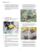
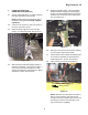
Big Country 4 x 2 1.4. If the operator of the vehicle has any specific brake performance complaints, these complaints should direct the visual examination and be confirmed during the operational test. If the operator describes an inherently unsafe condition, a complete inspection should be performed in lieu of the operational test. 2. OPERATIONAL TESTS 2.1. Operational be performed in a safe location that is free of traffic, obstacles and hazards. See Figure 2.1. 2.7.
Big Country 4 x 2 3. COMPLETE INSPECTION (DRUM AND SHOE REMOVAL) 3.1. Perform operational tests if no unsafe conditions have been described by the operator. 3.5. Engage the parking brake. Insure the parking brake assembly is engaging and disengaging properly. The latch (parking brake lever) should hook securely over the tab on the brake pedal arm. See Figure 3.5. NOTE: All brake repair work should be done in compliance with applicable OHSHA and EPA regulations. 3.2.
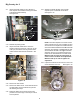
Big Country 4 x 2 3.9. 3.15. Slacken the brake adjuster using a brake adjuster spoon or flat blade screw driver. See Figure 3.15. Inspect the brake cables for any damage or wear. Inspect the hardware securing the cables to the brake pedal assembly. See Figure 3.9. Equalizer bar Brake cables Window in brake drum Star wheel Bellville washers Jam nuts Brake adjuster Figure 3.15 Figure 3.9 NOTE: The brake adjuster is the same on both sides of the Big Country, but is installed in opposite directions.
Big Country 4 x 2 3.18. Remove the “R” shaped clips securing the brake actuator to the brake shoes. See Figure 3.18. NOTE: If the friction material is contaminated with oil, identify the source, repair the leak, and replace the shoes. “R” Shaped clips NOTE: The friction material on the brake shoes should not be worn to a thickness of less than 3/32”. The friction material should not be contaminated with oil.
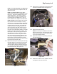
Big Country 4 x 2 3.22. Pry out on the base of the brake shoes while removing the adjuster. See Figure 3.22. 3.24. Remove the torsion springs. See Figure 3.24. Torsion Spring Blue extension spring Release from bottom lip using a screwdriver or brake spoon Brake adjuster Brake Shoe Figure 3.24 Figure 3.22 NOTE: Relieve the tension from the torsion spring by prying up on the bottom of the spring until it separates from the ledge on the brake shoe. 3.23.
Big Country 4 x 2 3.27. Assemble the brakes by reversing the shoe removal process. See Figure 3.27. 3.29. Adjust the brakes as described in the “Brake Adjustment” section of this manual. 3.30. After brake adjustment is complete, perform the operational test as described in the “Visual Inspection and Operational Test” section of this manual. Dust cover Brake mounting plate 4. BRAKE ADJUSTMENT 4.1.
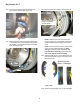
Big Country 4 x 2 4.4. 4.7. Disconnect the clevis on the end of each brake cable from the brake actuator extension arm by removing the cotter pin and clevis pin. See Figure 4.4. Set the adjuster so there is slight drag on the brake drum when turned by hand. Then adjust until no drag is present. At this point, play should be absent from the actuator. See Figure 4.7. Loosen Tighten Star Wheel Figure 4.4 Figure 4.
Big Country 4 x 2 BRAKE LINKAGE ADJUSTMENT: 4.9. 4.15. Secure the clevis pins with new cotter pins when adjustment is complete. Remove the fasteners that hold the hood closed, and open or remove the hood if it is not already open or removed. 4.16. If more adjustment travel is needed, or if the equalizer bracket is not level, the jam nuts at the front of the brake cable can be adjusted to correct the situation using a pair of 7/8” wrenches. See Figure 4.16. 4.10.
Big Country 4 x 2 4.20. When the parking brake is set, the brake switch actuator should release the plunger on the brake switch far enough to close the contacts within the switch. use a 3/8” wrench to adjust the brake switch actuator to achieve correct operation. See Figure 4.20. 4.18. There should be 7/8” (.875”) of free-play in the pedal before the pedal transmits movement to the cables. Free-play is measured at the front edge of the brake pedal pad. See Figure 4.18.
Big Country 4 x 2 4.22. Check to confirm that the parking brake indicator in the instrument panel illuminates when the parking brake is set. If it does not, it may be necessary to adjust the parking brake switch. See Figure 4.22. Parking Brake Switch Parking brake rod Parking brake arm Figure 4.22 NOTE: The parking brake switch is separate from the brake switch. 4.23.
Big Country 4 x 2 12
4 X 2 Drive Package: Dana Transaxle 1. ENGINE /TRANSMISSION CRADLE: DESCRIPTION The engine and transaxle are supported by a single structure that pivots on a “dogbone” link that connects the front of the cradle to the frame. The cradle and transaxle function as the Big County’s rear suspension. The engine must be held in a stable position in relation to the transaxle, in order to maintain tension on the drive belt. The engine is mounted to the cradle, and moves with the suspension. 2.
4 X 2 Drive Package: Dana Transaxle 3.7. The entire drive package and cradle can be removed from the Big Country 4 X 2 as an assembly if the technician has reason to do so. If the transaxle is to be repaired or replaced, the most direct method is to remove it from the cradle without removing the cradle from the frame. The amount of oil in the transaxle is 20 - 24 fl.oz.
4 X 2 Gear Selector 1. DESCRIPTION OF THE GEAR SELECTOR SYSTEM: 1.1. The gear selector on the 4 X 2 Utility Vehicle is electronically controlled and vacuum actuated. The operator selects the desired gear by pushing one of three buttons on the dashboard. The operator engages and disengages the differential lock using a yellow button to the left of the steering wheel. See Figure 1.1. Differential lock button 1.3. The brake switch is tied into the gear selector circuitry.
4 X 2 Gear Selector 1.5. 1.7. The electronic shift module (ESM) processes control inputs from the brake switch, neutral sensor, and the gear selector buttons on the dashboard. It figures out which way to move the shifting wedge to engage the desired gear. If a button is pushed, and the brake pedal is depressed, the ESM energizes the solenoids that control the vacuum to the servo that moves the shifting wedge. The ESM is mounted on the firewall, next to the brake pedal arm. See Figure 1.5.
4 X 2 Gear Selector • 1.10. The vacuum line marked with a blue dot provides vacuum to the actuator that controls the differential lock. The differential lock is engaged by a separate vacuum actuator. The differential lock is disengaged by spring action when two conditions are met: (1) The differential lock solenoid is not activated and (2) If the differential lock was previously engaged, the speed of the rear wheels is equal. The vacuum line with the blue dot should connect to the inner solenoid.
4 X 2 Gear Selector 1.13. The forward / reverse actuator is connected to the shift wedge. Depending on which side of the actuator vacuum is provided to, the actuator moves the shift wedge in one direction or the other. See Figure 1.13. 2. SELF DIAGNOSTICS 2.1. In the event of system malfunction, refer to the fault code list. 2.2. If the Big Country does not shift properly, the ESM will let the operator know there is a problem using the following table of fault codes.
4 X 2 Gear Selector 3. TERMS & DEFINITIONS - Code 2: “FORWARD” and “NEUTRAL” lights flash • ESM - Electronic Shift Module • • Neutral Switch - in the neutral position the switch is normally closed (NC). Action C - Vehicle is in "REVERSE" and operator shifts to "NEUTRAL" • This lets the operator know the vehicle was supposed to go to neutral, but probably ended up in forward. The vacuum actuator probably shifted the transmission into forward because the signal to stop at neutral was not present.
4 X 2 Gear Selector 4. 4.4. GEAR SELECTOR SYSTEM DIAGNOSIS EXPLANATION OF METHODOLOGY: • The gear selector system relies on two sub-systems (electrical and vacuum) to work properly. If either sub-system fails, the entire system will not operate correctly. • A complete decision tree for diagnosis would be unwieldy because of the number of variables involved.
4 X 2 Gear Selector 4.9. 4.11. Remove the two wing nuts that secure the hood, and open the hood. If the transmission fails to shift in response to the control buttons on the dashboard, and the shift wedge can be operated by hand with the engine off, check the operation of the transmission. • Manually place the shift wedge in neutral. • Set the parking brake. • Start the engine. 4.12.
4 X 2 Gear Selector 4.19. Check the operation of the neutral switch. The switch is normally closed. The contact roller should move freely, breaking continuity when the roller is pressed upward by the shift wedge. Adjust or replace if necessary. See Figure 4.19. 4.16. The ESM is visible on the firewall next to the brake pedal arm. Check the harness connection to the ESM for tightness, and check the condition of the wires leading to the ESM. See Figure 4.16. Electronic Shift Module .566” to.
4 X 2 Gear Selector 5. VACUUM TESTS 5.7. NOTE: The vacuum system is robust enough to function reasonably well, even with substantial leaks. The primary symptom of a leaky system will be failure to return to neutral when the vehicle is turned-off in gear. 5.1. With the engine off and the choke closed, release the clips that secure the air filter cover. Remove the air filter cover and air filter. 5.2. Remove the air filter base and air horn baffle using a socket wrench (10mm socket and 8mm socket). 5.
4 X 2 Gear Selector 5.9. If a vacuum gauge is connected by T-fitting at the reservoir (accumulator) end of the vacuum line from the intake manifold, the following readings should occur: See Figure 5.9. • Idle speed: pulsing needle 7 - 18 in. HG. • 2500 RPM: steady between 15 - 22 in. HG. (usually 17 - 18 in. HG.) • Over-run: highest reading > 30 in. HG. • Engine Off: vacuum falls to 0. 5.10.
4 X 2 Gear Selector 5.12. Disconnect and plug the fittings that lead to two of the solenoid valves. If the vacuum bleeds down quickly, the solenoid valve that is still connected is at fault. Reverse the test to confirm the results. See Figure 5.12. NOTE: The vacuum reaction is different from one side of the reservoir to the other because there is a check valve built into the reservoir. The reservoir also acts as a damper, smoothing out the vacuum levels variations and pulses.
4 X 2 Gear Selector 5.17. Identify the vacuum line from the reverse solenoid valve. Use a T-fitting to install the vacuum gauge in-line between the solenoid and the shift actuator (upper fitting). See Figure 5.17. NOTE: The vacuum line from the forward solenoid will have a red dot on the elbow that connects it to the upper fitting on the valve. The valve itself should be controlled by two wires: (1) Orange with white trace wire and (1) yellow with black trace wire. 5.16.
4 X 2 Gear Selector 5.19. If vacuum signals vary, check the electrical signal to the vacuum solenoid (see “Gear Selector Electrical System Diagnosis” section of this manual). 5.26. Repeat the test on the vacuum line that connects to the reverse side of the vacuum actuator. The results should mirror the results of the first test. 5.20. If the electrical system is functioning properly, replace the suspect solenoid valve. 5.27. If both tests work as described, the vacuum actuator is bad.
4 X 2 Gear Selector 5.31. The differential lock works independently of the gear selector, and is not controlled by the ESM. It responds directly to the yellow button to the left of the steering wheel. See Figure 5.31. 6. GEAR SELECTOR ELECTRICAL SYSTEM DIAGNOSIS. 6.1. Any time a computer controlled circuit is being checked, a high impedance circuit tester should be used. A conventional circuit tester simply places a light bulb in series with a ground path from the circuit being tested.
4 X 2 Gear Selector 6.3. If the fuse is OK, check the relay. See Figure 6.3. NOTE: Use this basic technique when checking any in-puts or out-puts of the ESM. If power is not found at the device that is connected to the ESM, check for power where the wire in question reaches the ESM. If the two do not correspond, a the problem lies between them, in the harness. Key to relay center 6.5.
4 X 2 Gear Selector 6.6. 6.10. The vacuum tests may identify a vacuum solenoid that is not working properly. Check the power to the solenoids to confirm whether the problem is in the solenoid itself or in the electrical signal to the solenoid. After power passes through the brake switch, it reaches the gear selector button on the dashboard. If power reaches these buttons, the brake switch contacts are closed. See Figure 6.6.
4 X 2 Gear Selector 6.14. If power is present at the second wire, that means that a ground path has successfully been created, and the vacuum solenoid should be open. See Figure 6.14. 6.17. The red wire with white trace wire will show power when the roller on the neutral switch is in the detent in the shift wedge. DIFFERENTIAL LOCK Vacuum test at the solenoid should correspond with the results of the electrical test 6.18.
4 X 2 Gear Selector 6.26. It will probably be necessary to rotate the input shaft of the transmission in order to allow the differential lock to engage. This can be done by grasping the driven clutch and rotating it. 6.22. The yellow wire from the button activates the differential lock solenoid. The green wire from the solenoid provides a constant ground. Check for power and vacuum at the upper port when energized. See Figure 6.22. 6.27.
4 X 2 Gear Selector 6.32. It will probably be necessary to rotate the input shaft of the transmission in order to allow the gears to mesh. This can be done by grasping the driven clutch and rotating it. See Figure 6.32. Figure 6.32 6.33. If the manual over-ride does not work properly, there may be an internal transmission problem.
4 X 2 Gear Selector 34