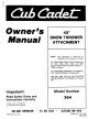
b Ca dell Owner’s 45" SNOW THROWER ATTACHMENT NOTE: The following is required to assemble snow thrower to tractor, ALL TRACTORS: FRONT PTO KIT Model 418 for 1100, 1200, 1250, 1450, and 1650 Tractors: Model 418 for 82 Series Tractors — 1980 to Present ALL TRACTORS w/MANUAL LIFT.
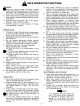
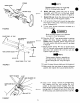
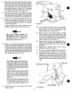
SAFE OPERATION PRACTICES AIMING Read the owner's guide instruction manual carefully. Be thoroughly familiar with the controls and proper use of the equipment. Know how to stop the unit and disengage the controls quickly. Never allow children to operate equipment. Never allow adults to operate equipment without proper instructions. Keep the area of operation clear of all persons, especially small children and pets. Exercise caution to avoid slipping or falling, when operating in reverse, PREPARATION 1.
ASSEMBLY INSTRUCTIONS This owner’s manual covers installation of the snow . thrower attachment to various model Cub Cadet tractors. Not all parts will be used for al! tractors. Follow only those instructions which pertain to your . unit. CONTENTS OF HARDWARE PACK (See figure 1): {4) Hex Bolts 1/2113 x 3" Long A f Ane B (8) Lock Washers 1/2" Hex Nuts Thread Hex Bolts 5" Long Clevis Pins 1/2" Diameter Beg Flat Washers 1/2" 1D, c—-E 288 G (6) Hairpin Cotters 1/2” Diameter B—g H (2) Hex Bolts x 3" Long* .
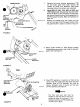
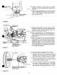
1. Remove the snow thrower attachment, PTO kit and loose parts from both cartons. Be certain all parts and literature have been removed before the cartons are discarded. 2. Model 680, HI-1282, 1210, 882, IH-782D, and 1512 tractors only: Disassemble the idler pulley shown in figure 2. Turn the pulley around so the IDLER PULLEY ' HOLE [ " hub side is toward the front, and reassemble to PTO the PTO support bracket. Refer to illustration on SUPPORT page 16. BRACKET ~a—me 3.
SPRING INNER HOLE FIGURE FIGURE 5 SQUARE TUBING 46" LONG LOCK WASHER (B) 10. HEX NUT {CH . LOCK WASHER (B} HEX NUT (G} 11 TUBING SUPPORT BRACKET HEX BOLT (A} HEX 8047 (O} SQUARE TUBING LONG FIGURE DRIFT CUTTER \ \\ LOCK WASHER (@ 3 14, CARRIAGE BOLT\ P -— #NOTE Disregard steps 6 and 7 for model 419 PTO kit. Proceed with step 8, Model 418 only: Hook ion end of spring {provided with PTO kit) 1o the bolt which secures the idler pulley as shown in figure 5.
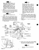
HEX LOCK NUT (T) GREASE THIS AREA -— CHUTE FLANGE KEEPER (8} FIGURE 8 COTTER PIN (X} LARGE FLAT éwmnen V) £s SUPPORT HEX BOLTS {Y) LOCK WASHERS {N} HEX NUTS {Z) FIGURE 9 P.T.0. SHAFT SPRING LOADED PORTION OF UNIVERSAL DRIVE SHAFT—-PULLED BACK FIGURE 10 15. 16. Grease the flange a1 chute opening of blower housing using all purpose automotive grease. See figure 8. Place the chute assembly over the chute opening using flange keepers (8) and hex center lock nuts {T. A 7/18" boxed or open end wrench is required.
FIGURE 11 NOTE 482, 580 {HI-582 Special and 1604 tractors: Disregard the following steps 4 through 11. For these models, go directly to step 12. 982, 984, 986, 1912 and 1914 tractors: Disregard the following steps 4 through 17. Install hanger bracket extension kit model 4271 {(see page 18). Remove the two hex bolts and spring washers from the lower end of the trans axle housing on the right side. Discard the hex bolts and save the spring washers for re-assembly.
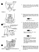
THREE POINT HITCH PLATE A PATCH BOLTS AND @ LOCK WASHERS DRAW BAR FIGURE 13 HEX BOLT (0 LOCK WASHER (N} ) URE 14 NOT USED FOR MODEL 482, 580 4-582 SPECIAL] AND 1604, USE THIS HOLE ON LEFT SIDE @ \ ONLY ® '\A PATCH BOLTS (0) LOCK WASHERS IN] FIGURE 15 CUT FIGURE 482, 580 {HI-582 Special} and 1604 only. n 12. Using the patch bolts and lock washers removed in the previous step mount the draw bar hitch plate to the three point hitch plate assembly. See figure 13.
The three point hitch plate mounts to the inside of the tractor frame. Secure the three point hitch plate to the right side of the tractor frame using two 3/4” long hex bolts (O} and lock washers (N} in the top two holes only at this point as shown in figure 15. For models 482, 580 {HI-582) and 1604 tractors, use only the middle bolt position. See figure 15, Secure the three point hitch plate to the left side of the tractor frame using only the top three holes at this point.
CONTROLS * The thrower controls are conveniently located at the ramrod's position on the tractor. LEVER The lift lever on the tractor is used to raise and lower snow thrower. To raise snow thrower, pull back on lift lever. To lower snow thrower, push lift Ever forward slowly until snow thrower reaches ground level, DISCHARGE CHUTE CONTROL CRANK The discharge chute control crank is located on the left hand side of the snow thrower. The chute crank controls the direction in which snow is thrown.
‘ NOTE When snow thrower and tractor are not in use, lower snow thrower to the ground to prevent excess weight on front tires. USE OF TIRE CHAINS Tire chains should always be used when extra traction is needed. They add maneuverability in handling snow removal jobs. groves A § warning § Tt es When making any adjustments, turn tractor engine off. SKID SHOE ADJUSTMENT The skid shoes are mounted on each side of spiral housing. These regulate distance shave plate is raised above the plowing surface.
'Model 364 Specifications subject to change without notice or obligation. ° -NOTE Lubricate with 4 oz. Shell Albania Grease PROOF. 737-0168. Order Part No.
Model 364 PARTS LIST FOR 45" SNOW THROWER MODEL 364 EF. REF, New ho. PART NO. DESCRIPTION NO. PART NO. DESCRIPTION Part 1 | 714-0507 | Cotter Pin 46 | 736-0250 | 1.00" 1.D.x 1.75" 0.D. 2 | 736-0140 | FL-Wash. 39" 1.D.x 62" O.D. 47 | 738-0492 | Spiral Axle 3 | 741-0475 | Plastic Bushing 48 | 741.0182 | Flange Bearing 1.503" 1.D. 4 | 7360140 | 62" 0.D. 49 1 7100891 |Shear Bolt x 1.75" Lg. 5 | 05982 Chute Crank Ass'y. 50 | 721-0146 | Oil Seal 1.50" 1.D. & | 741-0471 | Plastic Bushing 51 736-0266 | 1.D.x 2.
‘Model 364 Tracer SEE KIT ON PAGE 16 Lubricate with 8 o0z2. of plastique grease. Order Part No. 737-0133.
Model 364 PARTS LIST FOR MODEL 364 45" SNOW THROWER ATTACHMENT REF. NEW |REF. NEW NO. PART NO, DESCRIPTION PARTING. PART NO. DESCRIPTION PART 11 712-0240 Hex Jam Nut Thd. 33 | 7210188 Gasket 2| 7360171 7/16" 1.D.* 34 | 7500612 Spacer 1.00" 1.D. x 1.18" Q.D. 3| 750-0417 Spacer .50" 1.D. x 1.0" 0.D. x .440" Lg. x 1.47" Lg. 35 | 713-0346 11-2 x 500 Pitch Sprocket 41 710-3116 Patch Bolt x 2.5" La. Shaft Ass'y.
‘Modeler ' FOR 1100, 1200, 1250, 1450 and 1650 TRACTORS dole 419 FRONT PTO KITS -NOTE PARTS LIST FOR FRONT PTO KIT MODELS 418 and 419 Hub side towards the front on the Diesel and 680 tractors. REF. NEW [REF. NEW NO. PART NO. DESCRIPTION PART| NO. PART NO. DESCRIPTION PART 1 712-0266 Hex Cent. Nut 16 | 08253 Bearing Shield Thd. 17 | 741-0819 Ball Bearing .787" 1.D. x 1.85" 2| 7320470 Extension Spring .54" x 6.25" 0.D. Lg. 18 | 750-0456 Spacer 1.0" 0.D. x .790" I.D. 3| 712-0342 Hex Jam Nut Thd. x 350" Lg.
Model 420 MANUAL LIFT FOR ALL MANUAL LIFT TRACTORS HELPER SPRING KlT PARTS IN KIT A 12} 732-0488 Helper Springs D B {2} 710-0922 Hex Bolts x 6.0" Lg. C (2) 736-0242 Libreville Washers D {2} 711-0609 Spring Inserts HOOK ON FRAME HEX NUT (H} . LOCK WASHER (G} HEX BOLT (B} LIBREVILLE WASHER (C} INSTALLATION INSTRUCTIONS 1. Place vaudeville washers (C) on hex bolts (B (crown on side of washers go against the head of the bolts.
:Model 421 HANGER BRACKET FOR 982, 984, 986, 1912 and 1914 TRACTORS EXTENSION KIT PARTS IN KIT A (2) 703-0437 Lower Link Support Plates B {2) 784-5094 Rear Hanger Bret. C 1) 784-5104 Lift Bracket Lg. D (8] 710-3080 Hex Bolt 711-3085 Support Spacers F (4] 710-0601 Hex Wash. Hd. Self Tap Scr. x .75" Lg. G {6) 736-0169 Lock Washers 3/8” |.D. H (1) 784-5236 Adjustable Link Lg.
Cub Cadet Corporation Limited One Year Warranty For Outdoor Power Products Cub Cadet Corporation’s Promise To You We promise you, the first user purchaser, that we will replace or repair any part or parts of your new outdoor power product which is defective in material or workmanship without charge for either parts or labor during the first year following delivery to you.
_ MODEL 396 FOR ALL TRACTORS WEIGHT BOX KIT PARTS IN WEIGHT BOX KIT Reel earthen. DESCRIPTION artery 11 7845147 | Weight Box Ass'y. 1 2 | 7845208 Weight Box Support Ass'y, 1 3| 710-0515 Hex Bolt x 350" Lg. 4 41 7110775 Clevis Pin .50" Dia. x 2.75" Lg. 2 51 7th-0922 Hex Jam Nut Thd. 4 6 | 7140101 Inter Cotter Pin 1/2" Dia. 2 7 736-0272 .510" 1.D. x 1.0" 0.D. 2 8| 736-0921 L-Wash. 1/2" 1.D. 4 19 INSTALLATION INSTRUCTIONS 1. Place the weight box support assemblies (Ref.