Cub Camel Power Equipment Owner’s Manual 40" m) note SNOW THROWER ATTACHMENT Model Number 350 {190-350-100} Important: Read Safety Rules and Instructions Carefully Thank you for purchasing an American-built product. CUB CADET CORPORATION s PO.
1. IMPORTANT Safe Operation Practices for Snow Throwers TRAINING Read the owner's guide instruction manual carefully. Be thoroughly familiar with the controls and proper use of the equipment. Know how 1o stop the unit and disengage the controls quickly. 2. Never allow children to operate equipment. Never allow adults to operate equipment without proper instruction. 3. Keep the area of operation clear of all persons, especially small children and pets. 4.
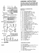
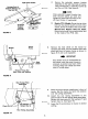
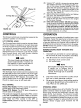
@ DRIP O fl —N R R ©@/Q — cove '@ FIGURE ASSEMBLY INSTRUCTIONS This owner's manual covers the assembly of the snow thrower attachment to various models of lawn tractors. Not all hardware will be used on all units. Follow only those instructions which pertain to your unit. CONTENTS OF HARDWARE PACK: {See figure 1) A {(2) Chute Flange Keepers Hex Bolts x long Hex Bolts x Long Hex Bolts x Hex Brits x 4 Long Hex Lock Nuts Thread Lift Bracket Pins Clevis Pins 1/2" Dia.
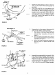
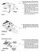
Huts —, Assembly Truss Machine Screw (AA) Flat Washer (AG) Hex Lock Nut Chute Flange j Keeper (A} FIGURE 2 Lock Washers (U) 3 Hex Nuts (1} Front Support Tubing Assembly LH. s Support \ Tubs Hex Bolts (E) Front Support Tubing Assembly RH. FIGURE 3 4, b and Hex Nuts (I} wad Plates FIGURE 4 Grease the chute opening on the snow thrower using a multi-purpose automotive grease or equivalent, Place chute assembly over chute opening, with the opening in the chute assembly facing the front of the unit.
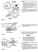
LH~ Hanger Plate assembly (W) FIGURE & FIGURE 6 AT Jack shaft Support Bracket Assembly FIGURE 7 Hex Bolts {AC) Lock Washers Assembly {V) oy A U-Bolt Carriage Bolt (J) Louisville Washer {Q) Hex Nuts (M) Attach the hanger plate assemblies to the rear of the tractor. Working on the right side of the unit, proceed as follows. A, Remove the nuts and washers which hold the transmission to the frame support bracket. On hydro static units, remove the U-bolt.
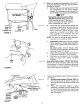
Right Hand Fender Carriage Lott {J) g Louisville Washer {Q} « Hex Nut (M) Jack shaft Support Bracket Assembly FIGURE 8 Tractor Remove These Two Brits, Nuts and Washers Heat Shield FIGURE 9 f Rear Hanger Plate (( Assemblies | U Flat Washer (T} Clovis Pin (H} Hairpin Clip (L} Roar Tubing Assemblies FIGURE Secure the jack shaft support bracket assembly on the right hand side of tractor, using carriage bolt {J), vaudeville washer {Q} and hex nut {M). See figure 8.
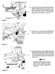
Lift Bracket Pin (Al) Ferrule (Al FIGURE 11 Flat Washer (T) Hairpin Clip (AK) FIGURE 12 RIGHT HAND SIDE OF TRACTOR Tubing Assembly on Snow Thrower FIGURE 13 N~ P Adjustment Link {AH) Ferrule Adjustable Hanger Link on Tractor I Hair Pin and Flat Washer from Mowing Deck 12. Units with serial numbers 126,001 and above: Attach adjustment links (AH) as follows. See figure 11, A Remove the cotter pin, flat washer and lift bracket pin which secure the lift cam to the lift link on each side of the tractor.
{1 Helper Spring Push Cap {AF) Bracket {AE} on Tubing FIGURE 14 Extension Spring (O} FIGURE 15 Idler Spring Front Idler Pulley Movable Idler Pulley FIGURE 16 . Assemble the beeper spring brackets (AE) as follows. a, Place push cap on weld bolt on helper spring bracket and tap on with hammer. b. Place hex bolt (B) through hole in helper spring bracket as shown in figure 14, ¢ Secure 1o tractor with Jock washer (S) and hex nut (K). Tighten securely. d. Assemble the other bracket in the same manner.
NN N O NSN NN Crank Support Tubing N Lock Washer (U} FIGURE 17 rank Support Tubing / / Outer Hole — 7~ Do Not Use i Hex Bolt (C) “Lock Washer {U) Hex Nut (M} FIGURE 18 In Inner Hole \ Lift Handle Stop Bracket (Z) Truss Machine Screw (AA} Libreville Washer {AB) FIGURE 19 AN 23. Assemble the crank support tubing to the snow thrower housing, using the inner hole in the housing as shown in figure 18. Secure in place with two hex bolts (C}, lock washers (U) and hex nuts (M). See figure 17.
Drift Cutter Hex Nut (M) FIGURE 20 26. Using a 1/2" wrench, remove the carriage bolts, lock washers and hex nuts holding the drift cutters t0 the snow thrower housing. Turn and place the drift cutters in position. Secure with the carriage bolts (J) (heads of bolts are to the inside of the housing}, lock washers {R) and hex nuts (M), See figure 20. 27. Adjust skid shoes to desired position and tighten hex nuts. See adjustment section. 28. Check tire pressure.
SNOW CONDITIONS Snow removal conditions vary greatly from fight fluffy snowfall to wet heavy snow. Therefore, operating instructions must be flexible to fit conditions encountered. The operator must adapt the «actor snow thrower to depth of snow, wind direction, temperature and surface conditions. DEEP OR DRIFTED SNOW In deep, drifted or banked snow, it will be necessary 1o use full throttle and first speed. Drive the spiral into the snow, disengage tractor drive clutch and allow spiral to clear the snow.
CHUTE DEFLECTOR ADJUSTMENT The upper chute deflector mounting on the top of the chute determines the distance snow is thrown. Moving top of deflector down decreases distance of throw and raising deflector increases distance of throw. Operator must get off tractor to make this adjustment. Disengage spirals and turn engine off before making this adjustment. To adjust, loosen hand knob on the side of chute deflector and pivot to desired position. Re tighten hand knob. See figure 22. « .
Model 350 PARTS LIST FOR MODEL 350 40 SNOW THROWER ATTACHMENT L def. New | Rof. New No. PART NO. DESCRIPTION Part| No. PART NO. DESCRIPTION Part 1| Ass'y. 62| 784-5081 |Spiral Housing Ass'y. 2 | 741-0227 |Flange Bearing 53 741-0309 |Self-Aligning Bearing 3 712-0158 |Hex Cent. L-Nut Thd. 54 741-0322 [Sieve Bearing .50 I.D. 4 1 .344” |.D, 55 ] 712-0267 |Hex Nut Th* § | 710-0323 |Truss Mach. Scr. x .76" 56| 712-0301 [Hex Nut Thd. Lg. 57 736-0367 L-Wash. 3/4” |.D.
Model 350 PARTS LIST FOR MODEL 350 40 SNOW THROWER Ref. New|Ref, New No. PART NO. DESCRIPTION Part | No. PART NO. DESCRIPTION Part 1| 710-0260 | Carriage Bolt 710-0786 | Hex Bolt 750-0641 | Sq. Tubing x 38.0” Lg. 2 | 736-0328 | L-Wash. 174" 1.D* 32 | 711-0510 | Clevis Pin 50" Dia. x 219" 3| 712-0138 | Hex Nut Thd. Lg. 4 | 714-0101 | Internal Cotter Pin 1/2” Dia. 33 [ 784-5120 | Hanger Plate 5 | 736-0272 | Fl-Wash. .510" LD. x 1.0” 34 | 710-0929 | Hex Bolt x 4.50" Lg.” OD. 35 | 741-0165 | Ball Brg. .62” I.D.