
Operator's Manual

17
D. INSTALL THE LIFT CYLINDER AND HOSES.
NOTE
The lift cylinder, elbows, hydraulic hoses, and
coupler fittings were preassembled at the
factory to ensure proper sealing of the
connections and position of the hoses (angled
slighly upward). Refer to the assembly drawing
in Figure 1 (Page 4) to verify proper assembly.
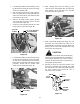
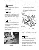
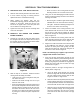
1. Remove the internal cotter pin and clevis pin from
the front end of the float arms on the pivot plate
assembly (See Figure 38).
Figure 38
2. Split the two float arms and position the piston of
the lift cylinder between them. Insert the clevis pin
through the arms and piston and secure with the
internal cotter pin (See Figure 38).
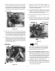
3. Remove the internal cotter pin and float setting
clevis pin from the float bracket (Refer to Figure
38).
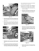
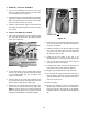
4. Pivot the lift cylinder upward to position between
the mounting brackets of the mounting plate. Insert
the clevis pin (M) through the mounting brackets
and cylinder and secure with the internal cotter pin
(N). See Figure 39.
Figure 39
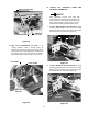
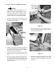
5. Route the hydraulic hoses around the left side of
the tractor and up through the pigtail of the hose
support rod (See Figure 40).
Figure 40
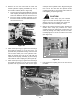
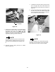
6. Remove the protective caps from both the male
and female coupling assemblies on the fitting
bulkhead. Snap the caps together to limit their
movement.
FLOAT
ARMS
INTERNAL
COTTER PIN
CLEVIS PIN
LIFT CYLINDER
ASSEMBLY
CLEVIS PIN
(FLOAT SETTING)
FLOAT
BRACKET
CLEVIS PIN
MOUNTING
BRACKETS
LIFT CYLINDER
HYDRAULIC
HOSES
HOSE
SUPPORT
ROD