Operator’s Manual HYDRAULIC FRONT HITCH ATTACHMENT For Cub Cadet Series 3000 Tractors (Optional Manual Angling Kit 190-171-100) INSTALLATION INSTRUCTIONS Model Number 343 IMPORTANT: READ SAFETY RULES AND INSTRUCTIONS CAREFULLY CUB CADET LLC P.O. BOX 361131 CLEVELAND, OHIO 44136-0019 [www.cubcadet.com] PRINTED IN U.S.A. ECO 07686 FORM NO.
NOTES 2
CONTENTS Section l Il lll IV V VI Page Safe Operation Practices .............................................................................................. To The Owner ............................................................................................................... Front Hitch Components ............................................................................................... Tractor Preparation .......................................................................................
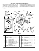
SECTION I. FRONT HITCH COMPONENTS Throughout the installation instructions in this manual, the component part name is followed by the reference letter or number in parentheses to aid in identification. Before beginning installation of the Front Hitch System, remove all parts from the shipping container. Refer to Figures 1 and 2 to confirm that all parts are present and to familiarize yourself with the part descriptions. 9 22 8 10 12 11 6 7 5 1 4 13 19 3 2 20 15 18 3 17 16 14 21 Figure 1 Ref.
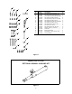
A B K C D L E F M G H Ref. No. A B C D E F G H I J K L M N 0 P Part No. 710-0805 710-0528 710-3025 712-0429 710-3131 712-3083 710-3104 712-3083 710-1058 712-0291 710-3013 721-3021 711-0578 714-0145 736-0159 721-0492 Description Qty. Hex Cap Screw, 5/16-18 x .1.5 ..... 1 Hex Cap Screw, 5/16-18 x 1.25 1 Hex Cap Screw, 5/16-18 x.625 GR5 2 Hex Insert Lock Nut, 5/16-18 ........ 4 Hex Cap Screw, 1/2-13 x 1.0 GR5 4 Hex Insert Lock Nut, 1/2-13 .......... 4 Hex Cap Screw, 1/2-13 x 2.
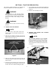
SECTION II. TRACTOR PREPARATION 4. Lift the locking tab of the connector and unplug the wire harness connector from the seat switch (See Figure 5). This section contains instructions for preparing the tractor for installation of the Front Hitch System. 5. Place the seat assembly to the side. WARNING Place the tractor on a firm and level surface, disengage the PTO, and turn the ignition switch to the OFF position. Chock the front wheels to prevent the tractor from rolling in either direction.
4. Loosen the four wing nuts securing the dash screen to both sides of the bulkhead; then slide the screen rearward and out from below the dash panel (See Figures 8 and 9) 1. From beneath the right running board, remove the hex wash. hd. tapp screws and remove in the following order: the reverse control pedal, forward control pedal, and the brake pedal (See Figure 6). NOTE: The following step 2 applies only to tractors equipped with the Diff-Lock feature. 2.
rearward as described in the following section D to increase the space. If the optional Hydraulic Angling Kit (190-288-100) is also being installed, the tank must be moved rearward. WARNING Use care when handling the fender and running board assembly. The edges could cause cuts to the skin. D. 1. Remove the two hex cap screws and hex flange lock nuts securing the top of the hitch plate to the frame (See Figure 11). 9.
SECTION III. INSTALLATION This section contains instructions for installing the Front Hitch System on the tractor. If the optional Hydraulic Angling Kit (190-288-100) is also being installed, refer to the installation instructions in its Operator’s Manual as you complete each of the following steps. Some of the instructions for installation of the Angling Kit will supersede or supplement instructions for the Front Hitch. A. REAR VALVE MTG.
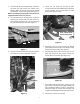
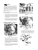
DOUBLE VALVE CLAMP NOTE Tractors built prior to Mfg. Code 1H018G have the standard center lift hydraulic lines routed to the outside of the frame. The standard lines should be moved to the inside of the frame to provide space for routing the front hitch hydraulic lines. The following step 5 applies ONLY to these tractors. HEX SCREW HYDRAULIC LINES 5. Move the standard lift cylinder lines to the inside of the frame as follows: a.
f. If not already installed, install a backup O-ring (P) between the existing O-ring and the flange of the front hydraulic tube. g. With the outlet ports facing inward, align the valve assembly with the front hydraulic tube and the slot ot the lift link, then slide the valve into position in the tractor. h. Slide the lift valve bracket w/nylon bearing onto the lift link and secure with the two hex cap screws (See Figure 18). i. 6.
9. Align the front port of the hydraulic valve (19) with the valve adapter (20) and the notch of the valve spool with the slot of the lift link (17); then slide the hydraulic valve into position behind the installed valve (See Figure 22). Hold the valve in position. SPOOL NOTCH LIFT LINK SLOT 12. Align the rear mtg. bracket hole with the slot in the lower/front corner of the frame opening and loosely install the previously removed hex screw and lock nut (See Figure 23). 13.
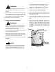
B. HYDRO RETURN TUBE (AUX. VALVE #1) NOTE O-RING BACKUP RING INSTALL THE HYDRAULIC TUBES AND COUPLING ASSEMBLIES. Early production tractors were built with running board mounting brackets welded to the frame, while later units have bolt up brackets. Note which bracket is used on the tractor to determine which fitting bulkhead will be used. 1. Tractors With Welded Frame Brackets.
outlet port of the hydraulic valve. Align the flanged front end of the tube with the tapered female coupling assembly (7) and loosely fasten with the tube coupling nut (See Figure 30). 3. Remove the hex nuts from both the male and female hydraulic coupling assemblies (6 and 7) and install as follows (Refer to Figure 29): a. From the front of the fitting bulkhead, insert the male coupling assembly (6) into the top inside hole of the bulkhead. Secure with the hex nut. CAUTION b.
2. Install the hose support rod (11) onto the left side of the mtg. plate assembly as follows (Refer to Figure 33): C. INSTALL THE FRONT HITCH COMPONENTS. WARNING a. Align the small loop of the support rod with the 5/16” hole, and insert the short hook at the bottom of the rod into the hole below. If the tractor has been recently operated, the muffler, exhaust pipe, and surrounding areas will be HOT. Allow the tractor to cool before continuing installation. b.
and reassemble with the two pivot pin assemblies and wingnut knobs (See Figure 33). QUICK LATCH BRACKET HEX CAP SCREW 9. If the front hitch components were installed as assembled and the mower deck is installed, reinstall the deck front hanger bracket as follows: a. Loosen the wingnut knob on the left side of the front hitch assembly. b. Remove the wingnut knob and pivot pin from the right side of the hitch to lower the right side of the pivot plate assembly (See Figure 36).
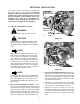
D. INSTALL THE LIFT CYLINDER AND HOSES. MOUNTING BRACKETS NOTE CLEVIS PIN The lift cylinder, elbows, hydraulic hoses, and coupler fittings were preassembled at the factory to ensure proper sealing of the connections and position of the hoses (angled slighly upward). Refer to the assembly drawing in Figure 1 (Page 4) to verify proper assembly. LIFT CYLINDER 1. Remove the internal cotter pin and clevis pin from the front end of the float arms on the pivot plate assembly (See Figure 38).
a. To allow the front hitch to float, insert the clevis pin in the upper hole of the float bracket and secure with the internal cotter pin as shown in Figure 42. COUPLING ASSEMBLY b. To set the front hitch in the fixed position, align the holes in the float arms with the lower hole in the float bracket and insert the clevis pin. Secure with the internal cotter pin.
SECTION IV. TRACTOR REASSEMBLY • A. REPOSITION FUEL TANK AND HITCH PLATE. 1. Slide the fuel tank fully forward in the frame slots. 2. If used, remove any plug or covering from the dipstick hole of the transmission housing. 3. While guiding the dipstick tube into the transmission opening, pivot the hitch plate up into position on the frame. Install the two hex cap screws in the upper holes of the hitch plate and secure with the hex flange lock nuts. 4.
C. REINSTALL THE SEAT ASSEMBLY. 1. Lay the seat assembly on its side on top of the fender and plug the wire harness connector onto the seat switch. Refer to Figure 5. LIFT HANDLE FLAP HANDLE SLOT (AUX. VALVE #1) LIFT LEVER COVER 2. Carefully position the seat assembly on the fender. Align the rear slide channel holes and fender holes with the mounting holes of the frame. Fasten with two torx head (or socket hd.) screws. 3.
E. CHECK OPERATION. If all previous installation procedures were correctly performed, the front hitch should raise when the lift handle is pulled upward (rearward) and lower when pushed downward (forward). If the opposite actions occur, switching the hose connections at the cylinder will correct the problem. Proceed a follows: HOSE FITTING ELBOWS CAUTION Position a suitable container to catch any oil leakage. Obey all applicable laws for disposal of oil. HOSE FITTING 1.
5. Reinstall the wingnut knobs to protect the threads of mounting plate studs. 6. The mounting plate can remain installed on the tractor. B. MAINTENANCE. Whenever the pivot pins are removed or once a year apply a light coating of high grade lubricating oil to the pins. LUBE FITTING Once a year lubricate the front angling pivot shaft with Cub Cadet 251H EP grease. Use a grease gun to apply through the front lube fitting (See Figure 49). Figure 49 SECTION VI.
MANUFACTURER’S LIMITED WARRANTY FOR: The limited warranty set forth below is given by Cub Cadet LLC with respect to new merchandise purchased and used in the United States, its possessions and territories. “Cub Cadet” warrants this product against defects in material and workmanship for a period of two (2) years commencing on the date of original purchase and will, at its option, repair or replace, free of charge, any part found to be defective in materials or workmanship.